
|
The Blue Lightning Transceiver/Receiver is a kit that provides circuit details, open source code and a large layout so the builder can learn theory and techniques on how a receiver/transceiver is designed. The double conversion receiver uses two 8-1/2" by 8-1/2" boards. Board 1 has the DDS VFO/Amplifiers, RF Amplifier/Bandpass Fiters, and First Mixer/Crystal Filter on three individual sections. Board 2 has the Crystal Oscillator/Second Mixer, 455kHz IF/AGC strip, and the 455kHz BFO/quad diode product detector/audio amplifiers on three individual sections. The receiver is built one section at a time with the two boards wired together for the final assembly. After building, the kit can be easily modified so new circuits and techniques can keep it up to date with continuing improvements in receiver technology. Pads for 12 Volt connections at each circuit block with easy in/out connections make modifications easy. A DDS VFO with offset switching, Varicap Bandpass Filters, and MOSFET amplifiers/mixers makes a simple, easy kit building experience. All the MOSFET amplifier/mixers are the same circuit for an easy building experience. The two Varicap Bandpass Filters eliminate relays so 60 through 10 meters are in small space. The 11 identical MOSFET circuits, for the mixers and amplifiers, are easy to build. DDS VFO Offset switching eliminates a mixer, oscillator and amplifier for simple transmit frequency output. The BLT offers a choice of DDS VFO circuits with a Microchip PIC or an Arduino Nano board for learning and using their respective language. The codes are open source with internet references on learning and developing the programs. The builder can learn and modify them for better performance and new features. They work "as is" if you aren't familiar with any programming. Both DDS VFOs (PIC and Arduino NANO) include receiver offset switching with the CW keying for effortless QSOs. The CW key automatically turns off the offset to change the VFO to the transmit frequency. A QRP T/R switch is built at the end of the VFO amplifiers for switching the output from the receiver to the transmitter and shapes the keying waveform for a great CW note. The 200 mW output can be used for QRPp operation or amplified to whatever output is desired. Varicap Bandpass filters cover 60 to 10 meters that can be expanded to the 80 and 6 bands with a change to the varicaps. The AADE Filter Design and W7ZOI PLPF Filters were used to design wide coverage with excellent isolation between the bands. Simple circuits used in the T/R switch and offset switching in the PIC/Arduino programming make it an easy transceiver to build and understand. The transmitter section is up to the builder. The BLT is a 200 mW transceiver. Any output level can be added. Builders can add transmitters already built or add kits sold on the Internet or described in homebrew articles. All the circuits for the transmitter section can be built Manhattan style or dead bug to keep expenses at a minimum.
ReceiverThe BLT includes the introduction of a PIC or Arduino Nano (your choice) DDS VFO (with the AD9850/AD9851 module) for 8 bands and offset elimination for transmit frequency output. The PIC code comes from the PIC-EL project (modified for transmit offset) and the Arduino code was written by W5UXS. The wider frequency coverage is handled with an expansion of the varicap tuned Bandpass Filters from 4 Bands (40, 30, 20 and 17 meters) with the ELR to 8 Bands (60, 40, 30, 20, 17, 15, 12, and 10 meters) with the BLT. 80 and 6 Meters are optional with a varicap added in the 60/20 Bandpass filter for 80 Meters. 6 Meters is added with a change of the varicaps in the 17/10 Bandpass filter (some other changes are needed). TransmitterA transistor/diode T/R switch has been added to the DDS VFO amplifiers to provide key shaping and a separate output for a transmitter. The receiver antenna is at the FM filter/RF Amplifier input so separate antennas can be used for transmit and receive if desired. If one antenna is used, a T/R switch is used at the transmitter output. The BLT is a 200 mW QRPp CW transceiver with a set of lowpass filters (not included) added to ensure FCC compliance. For QRP , a 5 to 10 watt CW transmitter can be tied to the BLT with Pi-resistive pads and keying if necessary. For older Boat Anchor Novice transmitters and 50 to 100 watt transmitters (homebrew or commercial), circuits are presented to interface these options. Most older tube Novice transmitters can be driven directly from the BLT. A couple of builds for the WA2EBY transmitter are presented with a 200 mW to 2 Watt amplifier and an RF T/R switch for single antenna operation. The 2 Watt amplifier can also be used with Novice tube transmitters (or 50/100 watt xmtrs) that require more drive than the BLT provides. Extensive information has been offered for transmit lowpass filter research, designing, and building filters appropriate to the power level chosen. A set of three lowpass filters and a set four Diplexer filters (for the WA2EBY or other MOSFET xmtrs) is presented for 40 to 10 Meters. The lowpass filters are sourced and built by the builder according to his need. A lowpass filter switch has been designed to select the proper lowpass filter with the tuning of the receiver Bandpass Filter pot making transceiver operation easy. All the transmit and lowpass circuits can be built Dead Bug or Manhattan style. The Manhattan style builds use one-eight inch traces and pads placed on transparent mirrored layouts with Blue Stick (Reusable Adhesive Putty) and then laid on a PCB board with Super Glue. This style is easy and inexpensive to build. Board 2Board 2 is the same with both the ELR and the BLT, remaining a single-sided PCB board, using the low noise MOSFETs in the IF strip and a Scotty diode balanced Product Detector for low noise and excellent audio. The crystal oscillator uses only one crystal with the BLT, a 4.000 MHz to beat with the two 3.547 crystal filters. Two 3.547 MHz filters are used with different bandwidths for individual preferences. One wide for general listening and one narrow for CW QSOs. The bandwidths can be easily modified. Board 1 UpgradesThe interconnections on Board 1 are infrared and provide AGC for the mixer input. The LEDs show switching functions, mixer drive levels, gain and diagnosis of the MOSFET amplifiers. Blue LEDs are suggested at various places that give the kit it's name: Blue Lightning Transceiver. If the blue is too intense, enough red LEDs are supplied to give it a more subdued look. They can be replaced by two series 1N914 diodes if it looks too much like a toy for the builder. Board 1 has been changed to a double-sided PCB board from the single sided ELR kit. This was necessary for inclusion of a DDS VFO in place of the Vackar VFO used in the ELR. 1. DDS VFO and Amplifiers - Board 1, Section 1 |
|
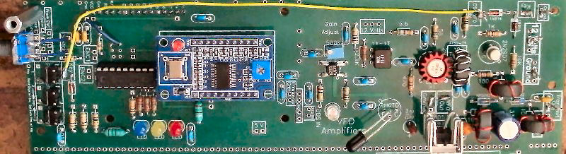
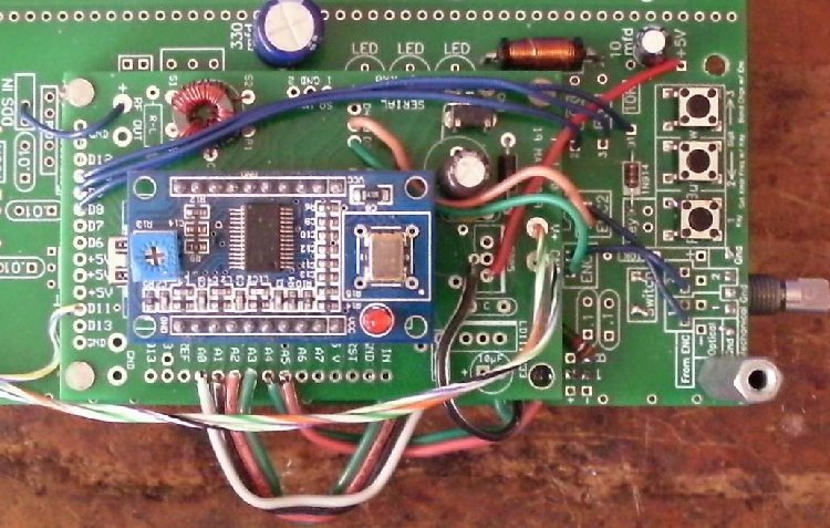
Board 1 has a simplified PIC-EL DDS VFO using either an AD9850 or AD9851 Analog Devices DDS using a Microchip PIC16F628 20/P or a PIC16F628A. These chips and the BLT programming has been tested on the 1st and 2nd version of PIC-EL Kit (click for details) and works well with a modification that disables the 2N2222 sound circuit. It may work on the 3rd version. The concept of a simplified PIC-EL was proposed by VK5TM and I asked for permission (granted) to use it for the BLT. His chart for the Ham Bands and one General Coverage Band was expanded further to include a Signal Generator (starts at 200 kHz) with no offset that can be used to find the frequency offset for the crystal filters. Additional programming included grounding an output pin of the PIC that would eliminate the frequency offset and key the T/R Switch at end of the VFO Amplifiers for transceiver operation. The VFO Amplifier gain was increased by using an AGCed LED MOSFET amplifier followed by an 2N5109 RF Amplifier, giving a very robust DDS Amplifier chain. Any DDS VFO kit or project sitting on your desk can be used for the kit. There is a DDS IN before the amplifiers to tie in any homebrew or commercial DDS VFO. Since the output for the transmitter is a T/R Switch following the DDS VFO amplifiers and the receiver antenna is at the FM Filter/RF Amplifier, separate antennas can be used for transmitting and receiving. One antenna can be used with a T/R switch at the transmitter output. An RF activated T/R switch circuit is described that works very well. The output is 200 mW and is adequate for almost all QRP amplifiers (some only need 10 mW and need a resistive pad increasing stability). A 2 Watt Amplifier (MRF 237) is added to the BLT output for driving most 50 and 100 Watt amplifiers, with a 3dB pad added for stability (for ones only needing 1 Watt of drive like the WA2EBY MRF510 amplifier). A black tube carries IR energy from the First Mixer (with an Infrared emitter) to the First DDS VFO MOSFET Amplifier. A 500K miniature trimmer is used at Gate 2 with the Phototransistor to set the gain of the DDS VFO Amplifier. The maximum output of the DDS VFO Amplifier chain is 9 to 10 V P-P. When drawn down to 4 V P-P with the 500K trimmer at Gate 2, the output is flat over the 7 to 30 MHz range. A 4 V P-P output to the mixer provides the best sensitivity versus dynamic range compromise with a low ambient noise level for comfortable listening with spurs and harmonics at low levels.The IR devices used are high emission and high sensitivity devices for best performance. For more information, check out DDS VFO and Amplifiers in the Circuit Details section. An Arduino Nano board is available for those who are interested in Arduino programming and would like an Arduino processor to run the DDS VFO. This board can be ordered in place of the PIC DDS VFO at no additional cost. The PIC parts will not be included. The programming works better for contesting and sprint CW contests. If you want both (extra $50), there is a stand alone PIC DDS VFO board. Since there is no provision for putting the switches, display or encoder on the Arduino board (they are tied onto Board 1), it is suggested to put the Arduino board on Board 1 and then building the PIC DDS VFO stand alone board, which has provisions for the switches, display and encoder.
|
2. Board 1, Section 2 - 8 Bands, 5.3 to 30 MHz |
|
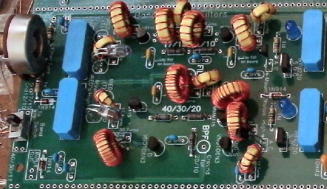
The Bandpass Filters were designed using an article written by Wes Hayward, W7ZOI, called a "Peaked Lowpass Filter" or a PLPF. Wes designed a Bandpass Filter with a dual section 400pf variable capacitor, four 3-microhenry inductors, and three shunt elements that covered 6 to 18 MHz. Upon inspection of this design, it looked perfect for the use of 400pf to 500pf varicaps that would be smaller in size and fit on Board 1 in place of the ELR Bandpass Filters. Extensive time was spent with AADE's Filter Design to find a filter that covered 60, 40, 30, and 20 meters using MVAM215 400pf varicaps, and one for 17, 15, 12, and 10 meters using MV2115 100pf varicaps. The most critical design element was the value of the shunt elements to get narrow peaks that gave isolation from the other bands in the filter. The DDS VFO, with the transmit function (offset removal) and these filters made a 7 band transceiver in the same board space as the ELR. More information and the charts from AADE's Filter Design can be viewed in the Circuit Details section: Blue Lightning Transceiver - Bandpass Filters DDS VFO with offset removalAn advantage of the DDS VFO, with programming to eliminate the offset when keyed, saves a lot of complexity and money in building a transceiver. Cost savings include a mixer, filter, and a couple of amplifiers. The simplicity of coming directly out of the receiver straight to the transmitter is very efficient. Any DDS VFO (with offset removal options) can be used with the BLT. Using an external DDS VFO with the BLT is quieter (spurs are lower) because isolation is improved when separated from Board 1 with a separate power supply. If you have one, you can order the BLT without the DDS VFO with a $50 discount. The simplified PIC-EL used on board is a great starting point with tons of documentation on the Internet and easy mods to the programming. After becoming familiar with the PIC-EL you can easily move on to more advanced designs. Building AidsEach board is three sections defining each functional section of the receiver. The mounting holes in the PCB boards are aligned for easy stacking, either whole or split apart. The topside of each board has a complete silkscreen for easy location of parts. Important instructions are silk screened on the board, so a hurried person will not miss important points. Included is a CD-ROM, with plenty of pictures, schematics, circuit details and pictorial instructions. The receiver is designed to work without a case. A bottom plate is not included with this kit so the connectors for 12 Volts, speaker, and antenna are mounted on the boards. One can mount a PCB or metal strip across the back attached to the spacers for the connections (not included). ConclusionIt is time to put a kit together with pictorial instructions, easily placed parts, and have the freedom to modify and improve. The result is a very good receiver that can be a working base for experiments, improvements and learning. The LEDs are a simple oscilloscope, providing diagnosis for the oscillator levels and operation. After the receiver is working, the LEDs contribute to an exciting visual experience. With the large board sizes with outlines of each individual circuit, it is an extensive, but easy kit to put together, while teaching you the concepts that make a receiver "bring in the signals". See "How Good is This Receiver?" for more information. Footnotes:The receiver was designed from concepts discussed in the following receivers from the 1970s to the present: "The Solid-State Receiver", by William Sabin, W0IYH, Design Problems and their Solution for High Performance, QST, July 1970, Page 35. "DX Receiver for the HF Bands", by Ovi Florea, WB2ZVU, This design features four Selectable front ends and excellent dynamic range to help you dig out the weak ones. Ham Radio, December 1976, page 10. Wes Hayward, W7ZOI, and John Lawson, K5IRK, "A Progressive Communications Receiver," QST, November 1981, Page 11. http://www.qsl.net/aa3sj/Pages/PR.htm Other references: [1] Wes Hayward, W7ZOI, "The Peaked Lowpass: a look at the ultraspherical filter, Use a pocket calculator for filter design, analysis, experimentation", Ham Radio, June 1984, Page 96. Used in the BLT. [2] Wes Hayward, W7ZOI, and John Lawson, K5IRK, "A Progressive Communications Receiver," QST, November 1981, Page 11. http://www.qsl.net/aa3sj/Pages/PR.htm [3] "Designing and Building Simple Crystal Filters", by Wes Hayward, W7ZOI, July 1987, QST, Page 24 The price of the kit is $179.95 plus shipping. |
|
|
|
|
Send E-Mail || Amateur Radio Receivers || Blue Lightning Transceiver || Ordering Information || Prices/Accessories
