

|
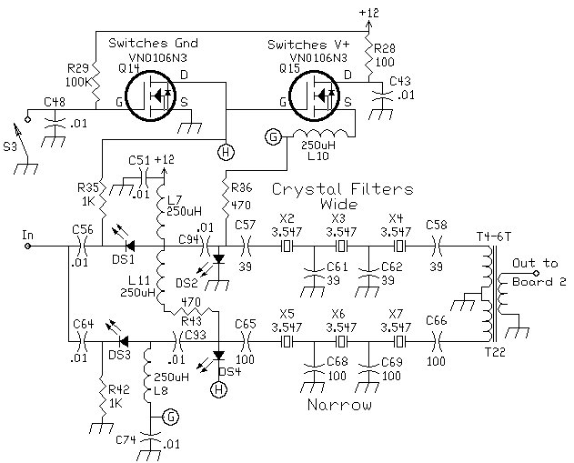
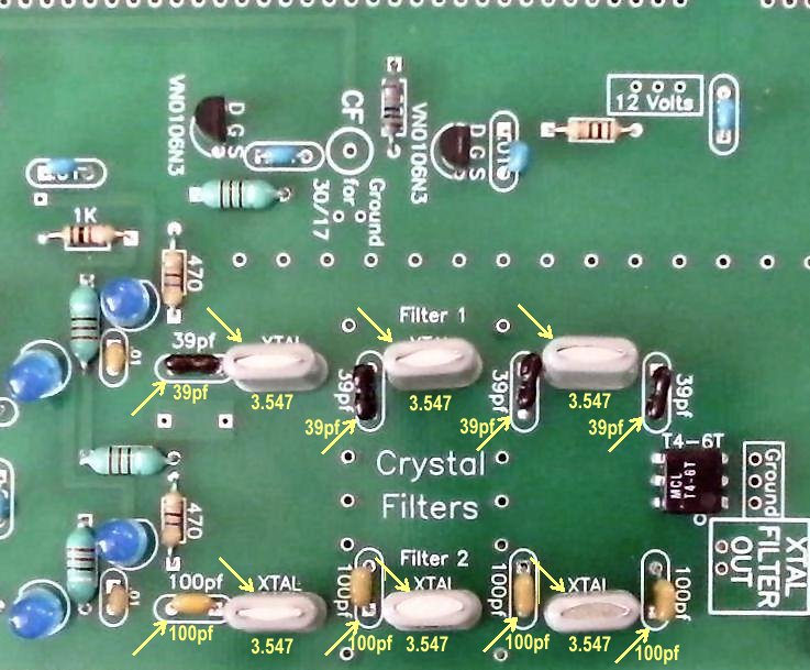
Using a DDS VFO, normally you only have the option of only one offset. Therefore both crystal filters have to be the same frequency. In this case, 3.547 MHz filters are used. One with 39pf caps resulting in a wide filter which works well for SSB and casual listening and the other with 100pf caps resulting in a narrow filter for CW operation. For information on this type of filter, check out "Designing and Building Simple Crystal Filters," by Wes Hayward, W7ZOI, QST, July 1987, P 24. These filters were made with the information from that article. References at the bottom of the page give more information on making crystal lattice filters to fine tune the responses of these filters. The IRED2 is used only if you are using two different crystal filter frequencies. In this case with both being 3.547 MHz filters, the IRED2 is replaced with an LED. The programming for the PIC DDS VFO has provisions for seperate offsets for each band, so if one wants to use two different crystal filter frequencies it is possible to do with changes in the programming to change the offsets according to the crystal frequency used with a specific band. For more information on this check out the PIC DDS VFO Program Code |
|
|
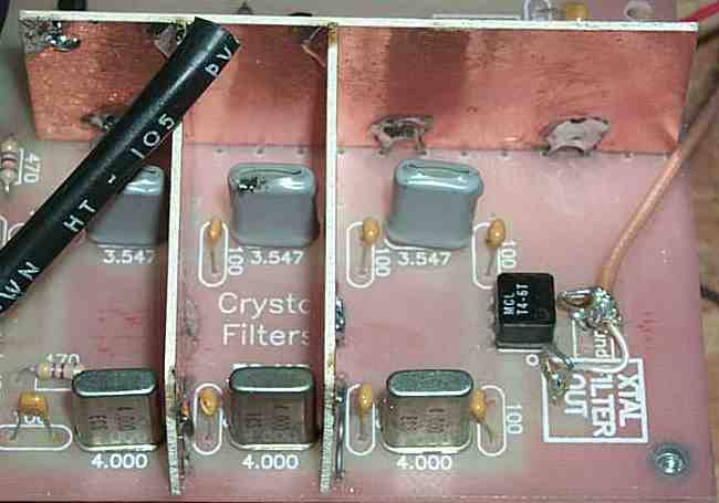
This picture is from the ELR, but the shielding technique is exactly the same with the Blue Lightning Transceiver.
The output of this board is the box labeled "Xtal Filter Out", with two soldering pads. The two pads are used to install a loop of wire for easy soldering and unsoldering during building and testing. The "Xtal Filter Out" is attached to the "Xtal Filter In" inside the box of the Second Mixer on the second board. Almost all the spurs in this receiver are the result of the VFO frequency getting into the second mixer. Always use shielded coax between the crystal filter output and the input of the second mixer to keep signal pickup to a minimum. Crystal Filter Inputs |
|
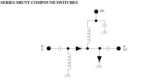
The diode swiching circuit shown above is called a Series-Shunt Switch using LEDs instead of PIN diodes normally used for this application. This circuit was added because the two diode series switch used with the ELR with different crystal filter frequencies for each filter (3.547/4.000 MHz) did not have enough isolation when the same crystal filter frequency (3.547 MHz) was used for both filters in the BLT. The first diode is the Series Switch which lets the signal pass when biased ON (LED on). When this LED is on, the second LED is off, the Shunt Switch, which shorts the signal going through it to ground. You want the second LED off in this case to allow the signal to pass freely into the filter. When a filter is turned off, the first LED will be Off and the second LED will be ON, shorting the signal through to ground. Whatever passes through the first LED when OFF gets shorted to ground with the Shunt Switch, which is ON and passes any remaining signal to Ground. A simple diagram of the Series_Shunt circuit is shown below. A single voltage is used to turn the dioded on/off, but notice the polarity of the diodes to the source of current. One is turned on at the same time the other is turned off. The implemenation of this circuit in the receiver schematic shown above is a little more complicated in that the ground and V+ are done with the VN0106N3 switching circuit. The first LED of each filter (series switch) is tied to the second LED (shunt switch) of the other filter. |
|
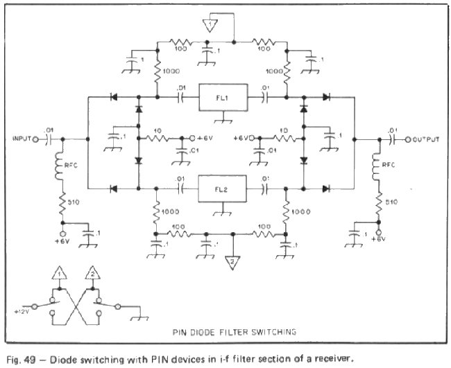
A circuit from Solid State Design, fig. 49, Page 91, shows input and output filter switches. In the case of the BLT, the input switch alone provided the necessary isolation and was easier to implement. |
|
Some references for more information on PIN diode switches are the following:
How-and-why-to-use-pin-diodes-for-rf-switching PIN diodes in RF switch applications References"Crystal Parameter Measurement and Ladder Cyrstal-Filter Design", QEX, Sept/Oct 2003, by Randy Evans, KJ6PO. Claims to have the easiest program for determining capacitor values for a ladder filter. Input crystal values into a spreadsheet program available at the ARRL QEX download site. Spreadsheet program file is 0309evans.zip. "Ladder Crystal Filter Design", by J. A. Hardcastle, November 1980, QST, Page 20. "A Unified Approach to the Design of Crystal Ladder Filters", by Wes Hayward, W7ZOI, May 1982, QST, Page 21. This was the first article that hinted at the fact that regular computer crystals or color burst crystals could be used in a very effective homebrew crystal filter. "Designing and Building Simple Crystal Filters," by Wes Hayward, W7ZOI, QST, July 1987, P 24. This article showed how using the same capacitance for each capacitor in a crystal ladder filter gave very good results, very inexpensively, and easily adjusted bandwidth. Crystal ladder filters - This page contains JavaScript tools to design and simulate crystal ladder filters which are widely used in SSB transmitters and CW receivers. Could be used to fine tune the xtal filters used in the receiver. Excellent page!
|

Send E-Mail || Amateur Radio Receivers || Blue Lightning Transceiver

