|
The bandpass filters used in this receiver are based on the article The Peaked Lowpass: a look at the ultraspherical filter, Use a pocket calculator for filter design, analysis, experimentation", Ham Radio, June 1984, Page 96, by Wes Hayward, W7ZOI. The main focus of the filters comes from page 104 with his discussion of the double tuned circuit of fig. 15B. The filters were run in AADE's Filter Design program to tune them for the bands of interest. Then they were built and small changes made to fine tune them.
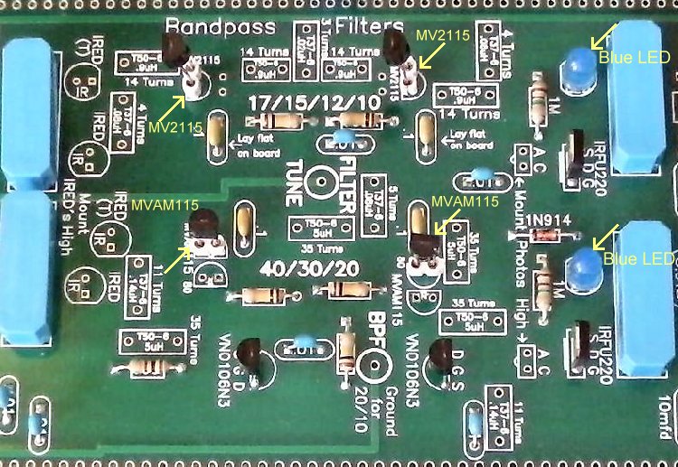
One filter covers 60, 40, 30 and 20 Meters with MVAM115 varicaps and 35 turn T50-6 coils. With one more MVAM115 in parallel, 80 and 60 Meters can be received. 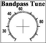 2-MVAM115 80/60/40/30 Meters Bandpass Label NOTE: There is a problem with 80 Meters because the Crystal Filter frequency, 3.547 MHz is in the 80 Meter band. Therefore, when there is a CW signal on that frequency, it will be an untunable signal that will be heard all over the band. Unfortunately, that frequency is one of the most popular frequencies for CW operators. If the band is open with many signals, that frequency will most likely have someone on it. If it is weak, tuning another signal on the band slightly off its tone can help copy. The second filter covers 17, 15, 12 and 10 meters with MV2115 varicaps. If the MV2115 is replaced with a MV2104, 6 Meters can be received. If the additional bands are wanted, SIPS are soldered onto the board, There are additional holes for a MVAM115 in which the SIPs are installed and the additional MWAM115 can be plugged in the 60, 40, 30, 20 BPF. With the 17, 15, 12 and 10 meter filter, the MV2115 is removed and a H66 or H65 (50pf varicap) put into its place for 6 Meters (the only band that it will tune). |
|
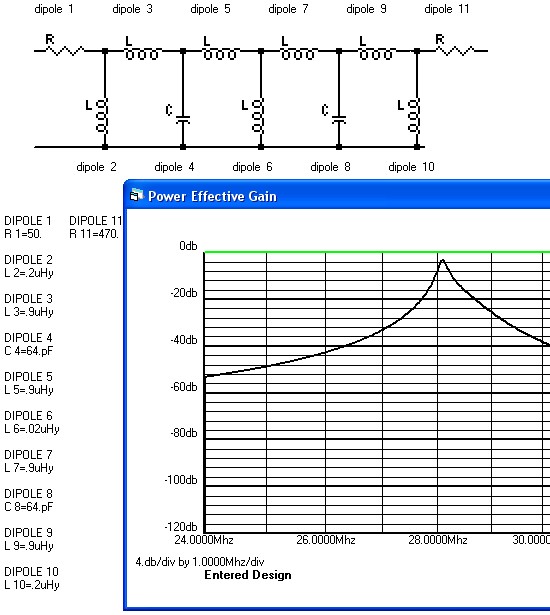
This filter design is based on the article "The Peaked Lowpass: a look at the ultraspherical filter, Use a pocket calculator for filter design, analysis, experimentation", Ham Radio, June 1984, Page 96, by Wes Hayward, W7ZOI. The filters come from page 104 with his discussion of the double tuned circuit of fig. 15B. These are based on the PLPF (Peaked Low Pass Filter) design taken to the extreme. A 5th order PLPF was used for the basic filter. This was cascaded with a 7th order high pass circuit to eliminate the low frequency response. Then the capacitive elements were changed to shunt inductors with reactances equal to the capacitors. Two interesting properties resulted. One was that the response shapes were very symmetrical. Second, was a wide tuning range was available. Note: The above material was taken directly from the noted article. A third one, pointed out by a person on a mail reflector, was that W7ZOI's design looked to be very adaptable to varicap tuning. The filters were run in AADE's Filter Design program with high capacitance varicaps: the MVAM series 500pf+ capacitance AM tuning diodes (specifically the MVAM115) and the moderate value MV2115 varicap for the upper HF bands. The PLPF bandpass filters with the varicaps proved to be a winning design. The 60/40/30/20 design uses one toroid more than separate filters, but with less board space. The 17/15/12/20 design saves one toroid than single filters for each band, but again, the board space saved is considerable. Also, the savings in relays for the different bands is a great space and monetary saver. The changes resulted in 8 bands in exactly the same space as the ELR with its 4 bands (40, 30, 20, and 17). Plus, it should be noted, all the frequencies in between can be tuned. With AM and digital detection methods added, this is a general coverage receiver from 7MHz to 30MHz. The performance equaled the modified Sabin varicap filters used with the ELR. Loses with the PLPF filters equaled about 3dB with all the bands, as shown in the Design Process below. This is a little higher than the 1-2dB loss with the Sabin filters, but is covered with the excellent 2N5109 RF amplifier. |
|
The MVAM115 Silicon Varactor Diode is used for this filter. Specification sheet shows a maximum of 560pf with a 15:1 minimum tuning range.. The tuning range used, as shown in the pictures below is 335pf for 60 Meters, 263pf for 40 Meters to 66pf for 20 Meters, is well within the range of this varactor. |
|
The MV2115 Silicon Varactor Diode is used for this filter. Specification sheet shows a maximum of 250pf at .1 Volt with a minimum of 70pf at 12 Volts. The tuning range used, as shown in the pictures below is 155pf for 17 Meters to 64pf for 10 Meters, is well within the range of this varactor. Tests done with a AADE L/C Meter with a .01 in series with the varactor showed 59pf to 160pf from almost zero volts to 12 volts. The value for T9 to T12 (Dipoles 3, 5, 7, and 9) was determined by using the capacitance value of the varactor with AADE's Filter Design program so that it would resonate in the bands wanted. Then the values for T13 and T15 (Dipoles 2, 10) were found that were -50dB to -60dB down at the adjacent bands. Then T14 (Dipole 6) was adjusted for minimum loss through the filter, the goal being about -3dB. Then back and forth between them to make the curve sharp and clean as possible. |

|
The limiting resistor for the LEDs is the coil resistance of the relays (500 ohms). There is also a small loss through the IRFU220s, which turn on the relays when gate voltage nears 4 volts as a result of IR energy hitting the IR diodes. The IR LEDs can be seen in front of the output relays. The switching circuit (two VN106N3's) supplies power to the output relays. The IR LEDs are in the ground circuit of the output relays, and they turn on the input relay through the photodiodes, on the opposite side of the bandpass filters. There is one additional IR LED in series with the one used for band changing. This one is normally shorted through with a PBC trace as it is only used when tied into the Lowpass Filter of a transmitter to switch it with the receiver Bandpass filter. That is why it is labeled (T), meaning Transmit IRED. Unfortunately, the Bandpass Filters and the Lowpass Filters do not have the sane range, as Lowpass Filters sometimes have 40 and 30 Meters together, and 20 and 17 Meters together, so they cannot be switched with the 60/40/30/20 Meter Bandpass Filter. But they were left in for a situation where they might be useful. Switching CircuitWhen power is applied to the receiver, 60/40/30/20 Meters is received (switches not installed or turned off). The 60/40/30/20 bandpass filter is turned on. VN106N3s and IRFU220s are used in the switching circuits. Only one wire, grounded by an SPST switch, is needed to switch the bandpass and crystal filters. The IR devices are used as simple switches. Infrared energy sent to an IR device turns it on, raising the gate voltage (to 4 volts) of an IRFU220 to turn on a relay (Bandpass Filter) or a crystal (Crystal Oscillator). When the receiver is turned on, the dual VN106N3 circuit turns on the 60/40/30/20 bandpass filter. To change to the 17/15/12/10 bandpass filter, the "Ground for 17/15/12/10" pad is grounded with an the SPDT slide switch. BG Micro carries the photo parts that are used in this receiver (IRED Part #LED1067). The IREDs that are used in the kit (LTE-4208C) are special high output types. This IRED was essential for the design of this receiver. I did find one on Ebay that looks like a black LED which had sufficient output to be used. Tuning the Bandpass FiltersTuning of the bandpass filters is done by a 100K panel mounted variable resistor. The value of this potentiometer can be as low as 10K and work well, and some kits may have this value when we run out of higher values. The footprint has a note "10K to 100K". A label showing the approximate location where the ham bands are tuned is at "Labels for the Receiver Dials." A fix for popping noise while tuning the Bandpass Pot is to ground the 100K potentiometer case. The ungrounded case can pick up stray RF from the bandpass filters and any RF floating around the receiver. A bare piece of hook up wire is soldered to the case and the nearest ground connection (blueltbuild12.htm#100K). There are ground pads on each side of the footprint for soldering ground wires for the case of the pot. |
|
An RF Gain Control can be implemented with a 400 to 500 pf varicap, a few resistors and a variable potentiometer. The value of the varicap is not critical as long it is of a high enough value to make a difference between its low value and high value capacitance. Any of the Hyper-abrupt varicaps used for AM radios will work. (MVAM series, MMBV series, MV16XX series) The RF Gain can be used in conjunction with the coupling capacitor in the "Narrowing the Bandpass Width" section to adjust your antenna farm to varying band conditions for the best reception. |
|
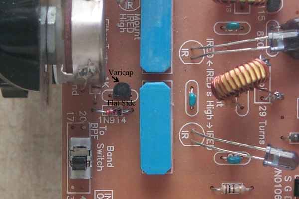
The .01 capacitor next to the 1N914 diode is removed from the board and the varicap is mounted in its footprint. The varicap is placed with its cathode toward the bandpass filter. There is another coupling cap on the cathode side so voltage can be applied in this position to vary the varicap capacitance. See the picture above noting the position of the flat side of the varicap. The anode of the varicap is grounded through the 5 turn winding at the input transformer of the mixer. |
|
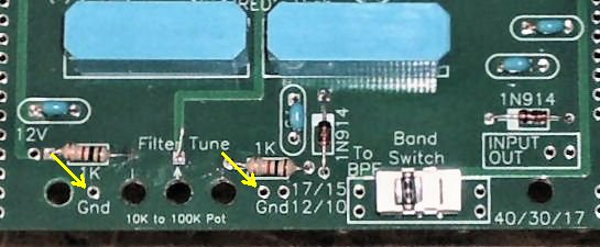
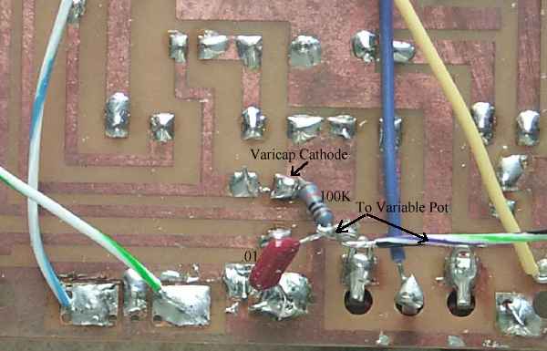
A 100K resistor and a .01 capacitor are mounted as close to the varicap as possible. One end of the 100K resistor is mounted at the cathode of the varicap, the lead closest to the bandpass filter relays. Next, one lead of a .01 capacitor is soldered to the ground plane of the PCB. Then both of the unsoldered leads of the resistor and the capacitor are soldered together. This junction is soldered to a wire that goes to the center terminal of a 50K or 100K potentiometer. The pot is mounted on the front panel of the receiver or to a piece of scrap PCB that mounts it at the front of the bottom board for easy access. A 1K resistor is soldered to each end terminal of the potentiometer, one 1K resistor going to a 12 Volt connection and the other 1K going to a ground connection. To make the control go from low gain to high gain as the knob is turned clockwise, solder the resistor on the left terminal to ground and the resistor on the right terminal to 12 Volts. |
|
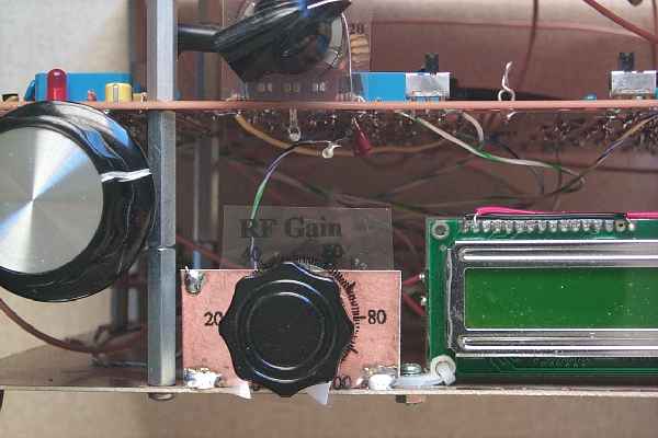
Picture showing RF Gain Control mounted on the bottom plate with a piece of scrap PCB. |
References[1] Wes Hayward, W7ZOI, "The Peaked Lowpass: a look at the ultraspherical filter, Use a pocket calculator for filter design, analysis, experimentation", Ham Radio, June 1984, Page 96. Used in the BLT. "Narrow Band-Pass Filters for HF", by William Sabin, W0IYH, September/October 2000, QEX "Double Tuned Circuits with Mixed Terminations - A Case Study." Wes Hayward, W7ZOI, April 20, 2008. A good article but can't find it anywhere. |
Board 1 || TV & FM, BC Filters || RF Amplifier || Bandpass Filters || First Mixer & Amplifier || Crystal Filter
Send E-Mail || Amateur Radio Receivers || Blue Lightning Transceiver