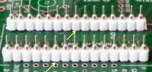
Top
Bottom
|
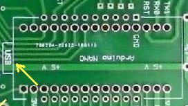
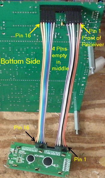
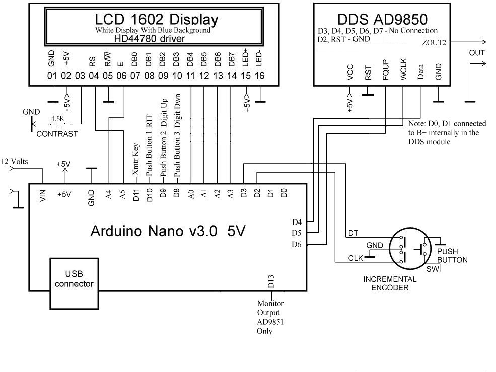
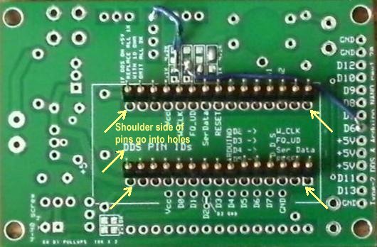
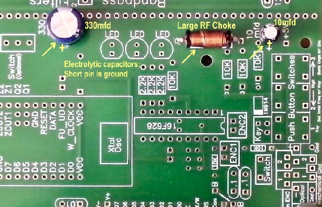
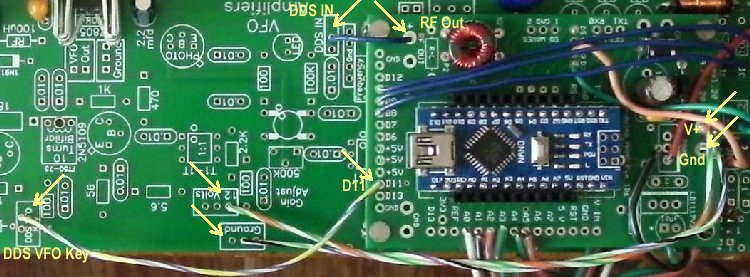
This board was originally used with the PHSNA "Poor Ham's Scalar Network Analyzer". The board was not modified so it could be used with the Network Analyzer build. This is a excellent, well built board with a very compact design. The connections to the DDS module from the Arduino Nano are different with the BLT. Modifications are made below so it would work with the BLT. 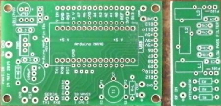 The board will be cut as shown above. The section to the right is not used because the -6dB Pi section attenuator can't be used with the receiver, the length with this section covers up the gain adjustment of the MOSFET DDS amplifier, and the low pass filter is not really necessary. If you decide you would like the low pass filter, it can be built and wired in between the output of the Arduino DDS VFO and the input to the MOSFET amplifier out of the way of the 500K MOSFET adjustment trimmer. (Parts not included with the kit.) Do not include the -6dB attenuator. Program code for the Arduino Nano is on the CDROM in the 'BLT CDROM Folder'. Open the CDROM in File Explorer and open 'BLT CDROM Folder' and click on the 'Arduino' folder. The program has already been loaded onto the Nano before shipping and does not need to be reloaded. It is primarily for study and modifications if you are familiar with the Arduino code. |
|
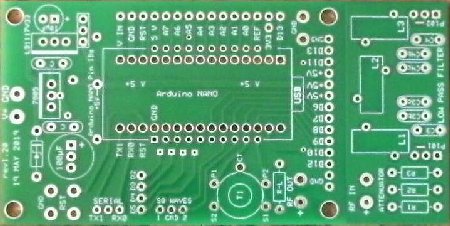
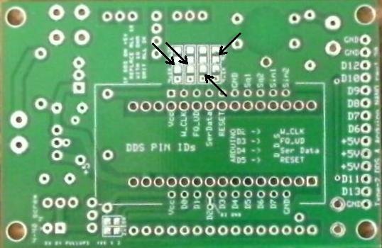
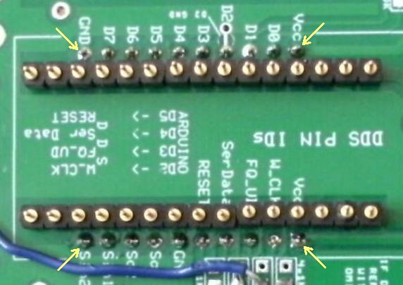
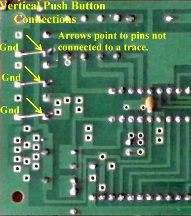
The two arrows on the left indicate where wires will be soldered going to D5 and D6. The two arrows on the right indicate pads that will be soldered together with a short jumper or a blob of solder. |
|
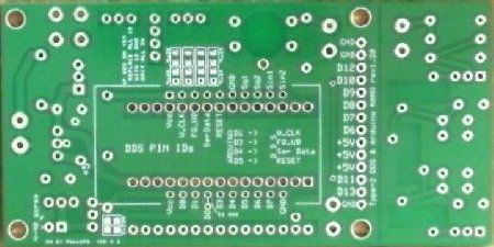
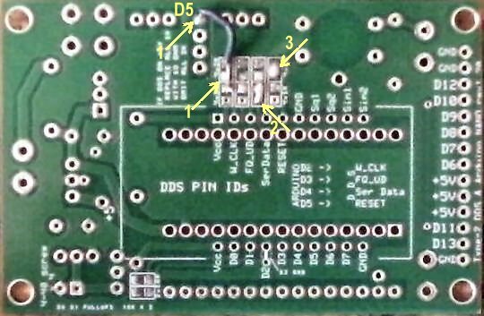
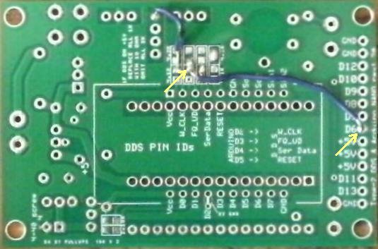
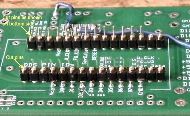
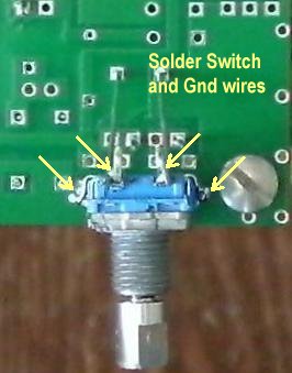
The picture above shows three of the modifications. D5 WireThe left one is where a 3/4" wire is soldered to one or both of the middle pads and run to the hole indicated which is D5, labeled on the other side of the board. This connects W.Clk to D5. Be careful: do not solder or connect to the top pad which goes to Ground. 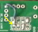 Solder JumpersThe second modification is shorting the hole and pad shown in the picture below at the third group of pads. An L shaped wire can be placed in the hole to help run solder between the square pad and the bottom hole below. This runs 'serData' to D4. The two middle pads are connected together on the PCB. 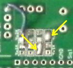 The third modification is placing a blob of solder between the top two pads at the fourth group of pads. This grounds the Reset of the DDS module. The two middle pads are connected together on the PCB. This a also shown in the above picture. |
|
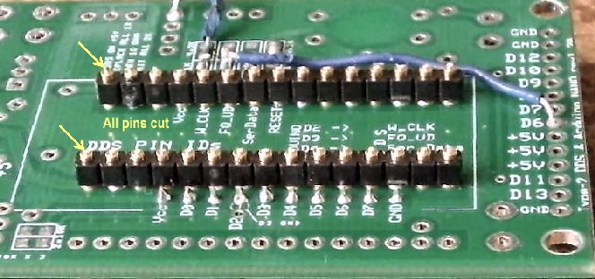
The fourth modification is running a 1-3/4" wire between the two middle pads shown above to D6 at the right side of the board. This connects FQ_UP to D6. 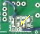 Be very careful not to short to the bottom pad as this will cause a malfunction with the encoder - it shorts D3 (encoder pin) to D6. |
|
This completes all the modifications. Mounting the Arduino Nano and the DDS Module is next. |
|
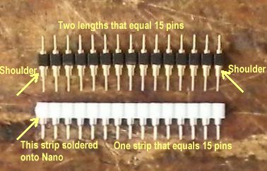
Shown above are the strip pins that will be used. Notice the top strip has a shoulder on the bottom pins. This shoulder will go into the PCB and be soldered to the board. The bottom white strip will be soldered onto the Nano, and the Nano will be plugged into the top strip that is soldered onto the board. |
|
Notice which side of the board is up: The side with 'DDS Pins IDs'. Arrow points to the text. The shoulder side of the pins goes into the holes which are a perfect tight fit. |
|
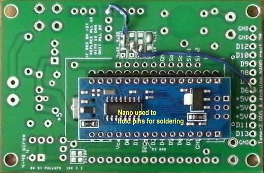
Then place the Nano over the pins and turn it over carefully to solder the pins. The Nano's purpose is to hold the pins straight until the four corners of the strip pins are soldered, and maybe a couple more, to ensure everything will go together without a problem. |
|
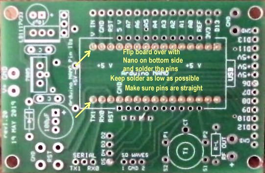
Solder each corner first, making sure the board is level and the pins are straight up. Keep the solder as low as possible, letting the solder flow into the holes soldering the shoulders onto the sides of the plated through holes. Use the finest solder you have and go slowly. If you see you might have too much, use a solder sucker and suck up the excess. The solder that flowed into the plated hole will stay and hold the pin. |
|
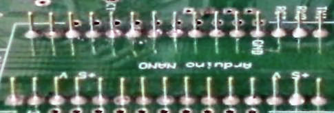
Picture showing the soldered pins. The following step will show up any pins that have too much solder. The white strip will be angled upwards. Take a solder sucker and remove some solder.
|
|
The 15 pin white strips will be plugged into the pins just soldered. Notice how the white strip is almost flat against the PCB. If any are pushed up some, remove the white strip and take some excess solder off the offending pin. Use a utility razor blade to help remove the white strip or a very small blade screw driver. |
|
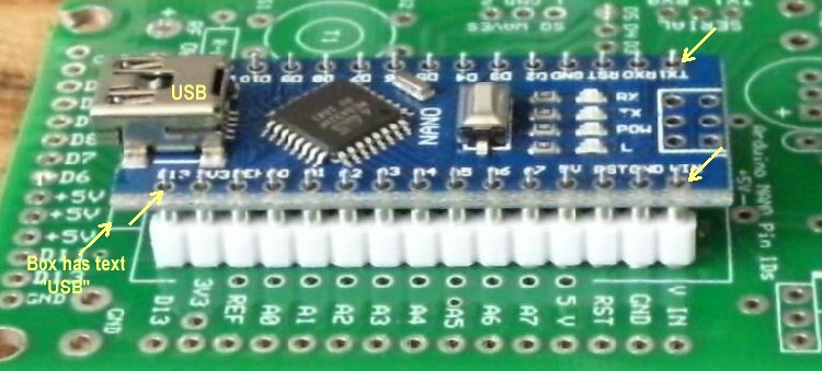
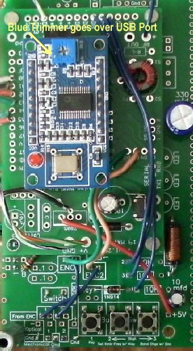
The Arduino Nano is placed on top of the white strip pins. Notice the USB box on one end as shown in the picture below:
This is where the USB port on the Nano should be placed as shown in the larger picture above. |
|
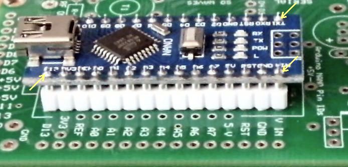
Arrows point to the rows of soldered pins. The upper left pins are blocked by the USB port in the picture. Carefully solder the four corners making sure the pins are straight and as centered as possible in the holes. Finish soldering the rest of the pins onto the Nano. |
|
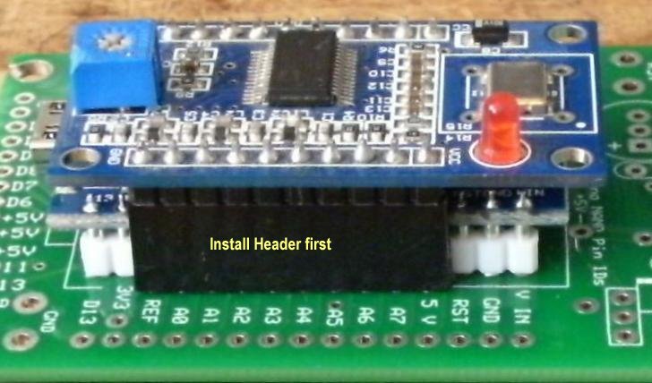
Get the 10 pin tall headers and place them in the holes next to the installed Nano as shown in the picture above. Then plug the DDS module into the headers. |
|
Turn the board over and solder the four corner pins. Have the a little pressure against the pins so that the headers are soldered flush onto the PCB. Then finish soldering the rest of the header pins. |
|
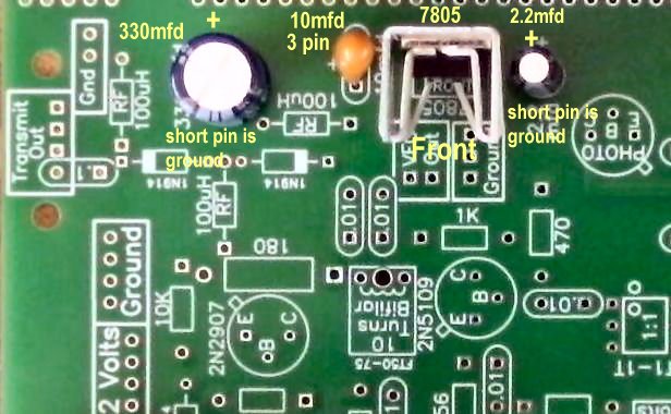
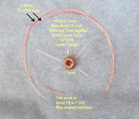
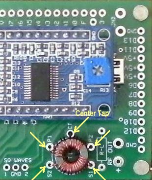
____1 - Large RF Choke 83uH ____1 - 330 mfd Electrolytic Capacitor, short lead is ground side. ____1 - 10 mfd Electrolytic Capacitor, short lead is ground side. When soldering the capacitors, you may want to push against the top of the capacitor while soldering the first lead so that they are flat against the PCB. |
|
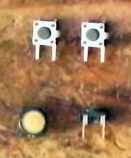
____3 - PC mount Push Button Switches. |
|
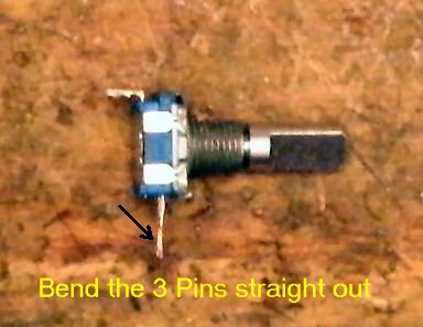
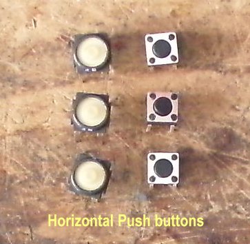
There are three kinds of Push Buttons, one vertical and two horizontal. The vertical ones have two leads (Upper left hand picture) and the horizontal have four. The horizontal ones have two leads connected to one side of the switch and two leads connected to the other side of the switch. One set of vertical and one set of horizontal will be included with the kit. The vertical buttons need to have the side tab bent to provide stability for the switch. The tab is bent as shown below and soldered to the plated through hole in front of the tab. 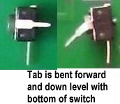 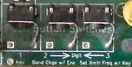 Second, the vertical buttons need a jumper to ground one side of the switch. |
|
The black horizontal ones (with large white buttons) are soldered onto the board with no modifications. They drop into the holes for the switches. The silver ones with the small buttons: 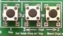 Be careful pushing them into the board to get them to set flat on the board. |
|
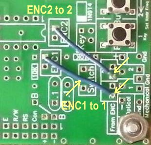
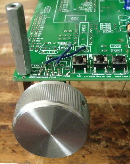
The Top Mounted Encoder requires moving the corner spacer to give room for a knob but is the most secure. Easy to use the encoder switch as you push down with stable operation. Top Forward Mounting Encoder is the most convenient to use. Four wires, two for the switch and two to ground hold the encoder firmly for easy rotation. The Bottom Forward Mounted Encoder allows the easiest access to the switches. If you will be using RIT (switch 1) a lot, you should consider this option. If after using the encoder for a while and it works intermediately, one of the pins of the encoder has broken inside the PCB hole. To fix this, the broken lead will move when heated with solder. Remove the broken lead and solder the other side of the lead on top of the board (or bottom depending on top or bottom mounting) with a fine soldering tip. You can also opt to solder the top and bottom of the leads to the PCB when installing the encoder. Review the instructions for each mounting first and decide which one you would like. Notice a small notch was made on the top corner (two pins) of the encoder to remove a curved spring to eliminate the clicking for effortless turning. Rotary Encoder Top MountingWhen using a Top Mounted Encoder, in order to use a knob the spacer at the corner will have to be moved to the right and the holes drilled with a 9/64" drill bit. The bottom spacer can be held with a nut and 2 screws will be needed at the new location for the upper spacer. The longer spacer 1 7/8" (double female) will be used between the boards and the smaller ones for the bottom. Note: The Mechanical rotary encoder included with the kit has a metal bottom. This will short out the pads underneath the encoder. Place a piece of black tape over the pads that will be under the encoder or place a piece of black tape on the back of the encoder as shown below. 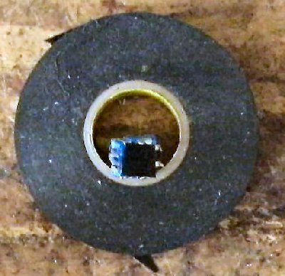 Connections need to be soldered between ENC1 to 1 and ENC2 to 2 in the encoder connection box. 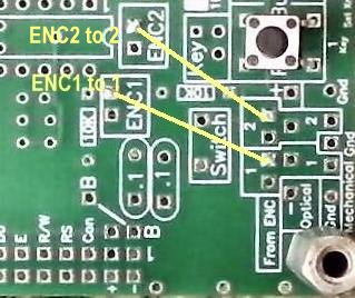 The connections to the box have to be soldered to the bottom of the board to prevent a short to the bottom of the encoder. Two lengths of 1" wire will be used. See pictures below. 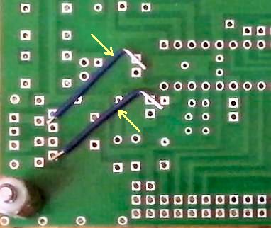 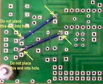 Install the encoder as shown below. There is a box labeled Switch through which the two leads will fit. This switch is connected to Button 3, which is used to set the transmit frequency with Button 1, connected to the transmit key (or pressing the key when connected). 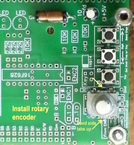 Note new location of the spacers in the above picture.
|
|
Bottom Mounted Encoder
When the encoder is mounted underneath the board, the rotation for increased frequency is reversed. The Encoder wires from the PIC have to be reversed so that turning the encoder clockwise will still increase the frequency. Use two 1-1/4" wires, one will go from ENC1 to 2 inside the encoder mounting box, and one will go from ENC2 to 1 inside the encoder mounting box. 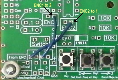 |
|
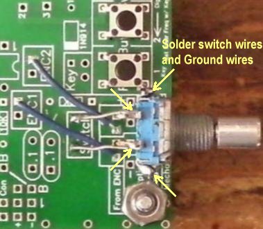
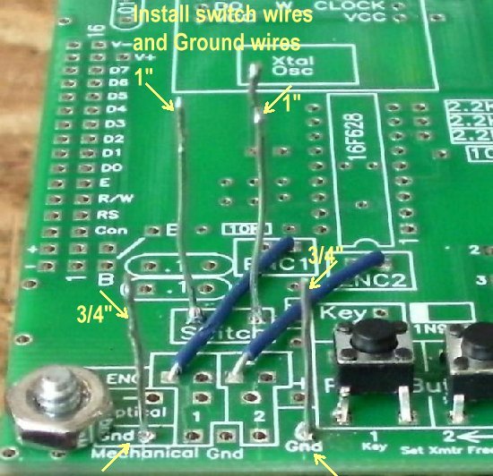
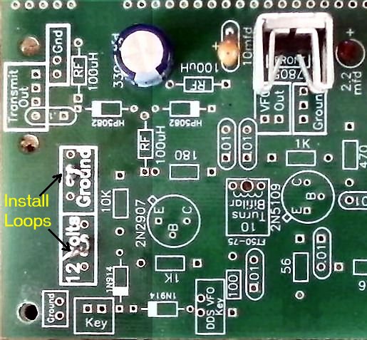
Two 1" bare wires (#22 or larger) are soldered in the Switch Box and two 3/4" are soldered in the two Gnd holes one each side of the mounting holes for the encoder. Make a small 90 degree bend at the top of the wires to hold them while soldering. 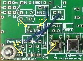 Next, install the encoder from the bottom side of the board and solder the leads at the top of the board. 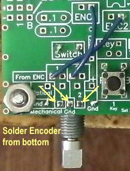 Turn the board over and solder the switch wires to the top two leads of the encoder. Straighten these wires and solder the leads close to the encoder as shown. Bend the side tabs forward and inward toward the body of the encoder. Solder the Gnd wires to the tabs on each side of the encoder and then trim extra lead length. |
|
With this mounting, the longer 1 7/8" spacer is used on the bottom and the shorter spacer 1 1/4" is used between the boards. The switches are easily reached with this mounting. |
|
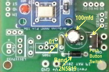
Mounting screws and nuts: ____3 - 4-40 screws, 5/8" long, other screws sent with the kit may have different heads. Then ones shown almost lay flat on the board. 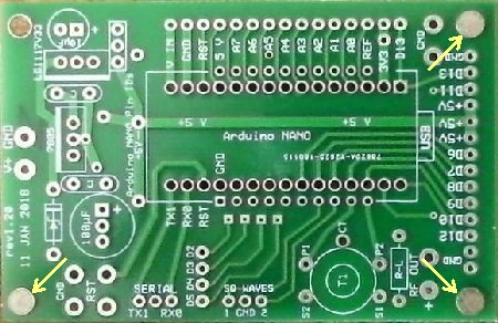 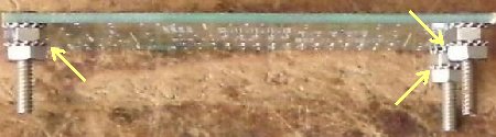 Place 3 4-40 screws in the places shown in the top picture. Notice which side that is the top side. There are only 3 holes on Board 1 to mount the Arduino board so the fourth hole is left empty. Shown in the second picture are the screws mounted using two 4-40 nuts. Two are needed to mount the board high enough to clear the bottom of the spacer that holds the Nano and the solder joints so they don't short against Board 1. There will be three 4-40 nuts left over to mount the Arduino board to Board 1 when it is ready to be attached to Board 1. ____1 - .1 capacitor ____1 - 100mfd/120mfd Electrolytic, 35/25V ____1 - 1N5819, Schottky Barrier Rectifier, 1 amp ____1 - Push button switch (for reset) |
|
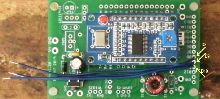
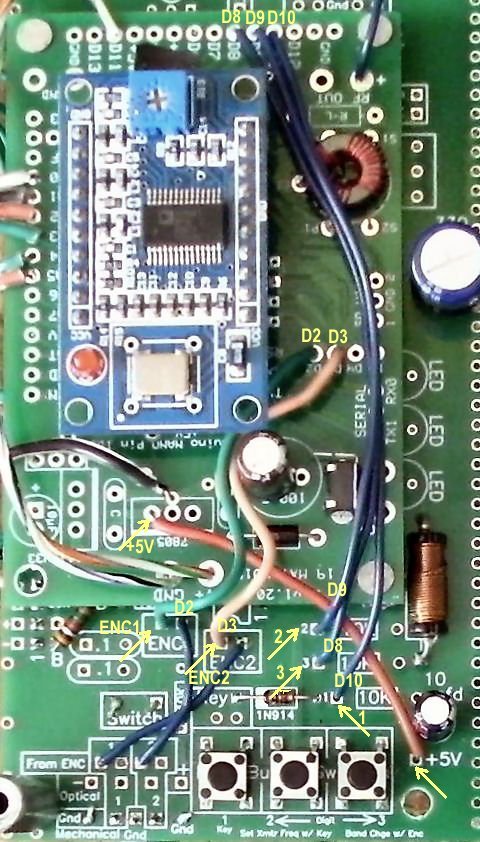
Make sure wire is stripped where you are soldering it underneath the board to be sure you are getting a good connection. Wires to Board 1Cut three insulated wires 4 inches long. Trim about 1/8" insulation off each end. Solder one wire to D8 (Digit Down), one to D9 (Digit Up) and one to D10 (RIT). These will go to the Push Button Switches at the front of Board 1. The wires as shown below should be moved down to the edge of the board. The reason is to have D2 and D3 exposed for connections to the encoder in a later step. |
|
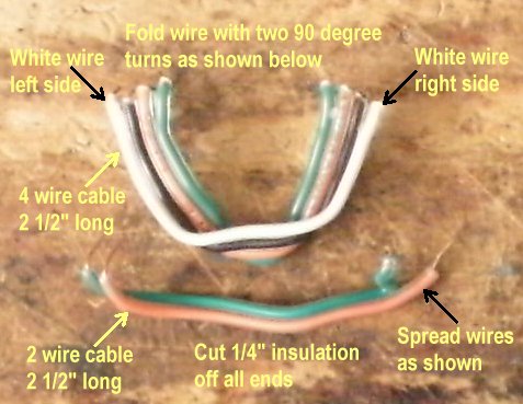
To make the 90 degree turns in the four cable wire, lay it down flat. About 1 inch for one end, lay it over at a 90 degree angle, then turn it over and about 1 inch from the other end, lay it over at a 90 degree angle. Press down with some force so it will keep it's shape. With the two cable wire, on the end where it solders to Board 1, they go in Pin 4 and Pin 6, so they need to be separated some to leave room for another wire that goes from Ground to Pin 5, which will be installed later. |
|
____2 - 2 1/2" colored wires for D2,D3 to ENC1, ENC2
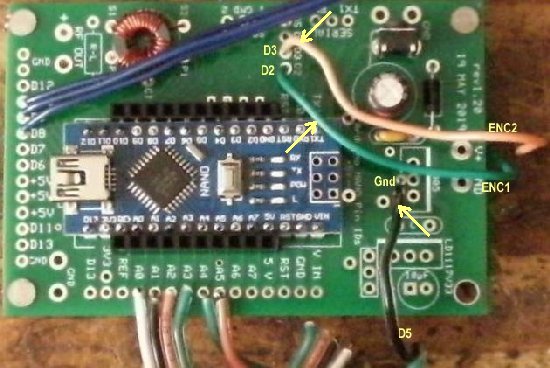
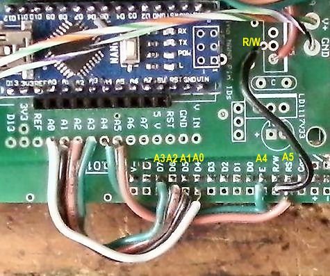
The wires coming from D2 and D3 are encoder wires that determine rotation. D2 goes to ENC1 on Board 1 and D3 goes to ENC2 on Board 1. Only solder the wires to the Arduino board at D2 and D3 for now. These wires will be routed down next to the PCB between the 100mfd electrolytic and the Nano toward the front to go to ENC1 and ENC2. The blue wires for the switches will go above these wires between the 100mfd electrolytic and the Push Button reset switch. ____1 - 2" Black wire for Ground wire to R/W connection of the LCD displayA black wire is soldered to a small plated through hole next to the center connection (ground connection) of where a 7805 voltage would go. The 7805 is not installed. The black wire will be going between the two wires for E (Pin 6) and RS (Pin 4) and grounds the R/W connection at Pin 5 of the LCD display. |
|
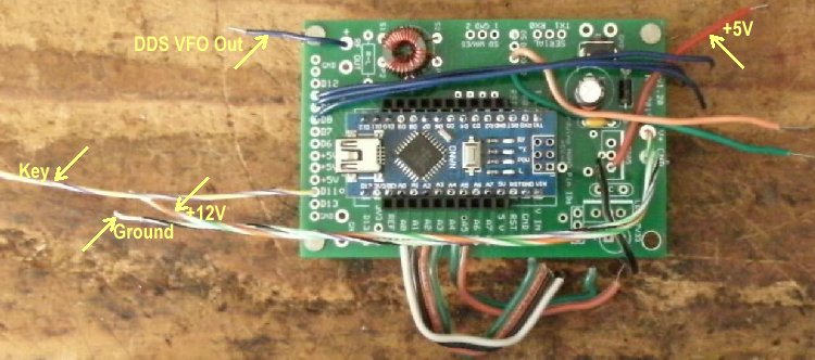
A 2 1/4" wire will go between the 5 volt side connection of the 7805 regulator footprint to the +5 connection in front of the 10mfd electrolytic at the right front of Board 1. Two 5 1/2" wires will connect to the V+ and Gnd connection at the front of the Arduino board at boxes marked 12 Volts and Ground half way down Section 1. One 4" wire will go from D11 to the box 'DDS VFO Key' near the back left side of Board 1. One 2" wire will go from "RF Out +" to the DDS In box in front of the Arduino board. |
|
____1 - 1.5K resistor
Install brightness resistor on Board 1. Bend the leads as shown: the footprint is too short to accept the resistor with the leads straight down. Install as shown below. Goes into the holes marked 'B' (short for Brightness) 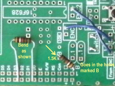 ____1 - 1N914 diode, match black band to band on footprint 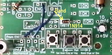 |
|
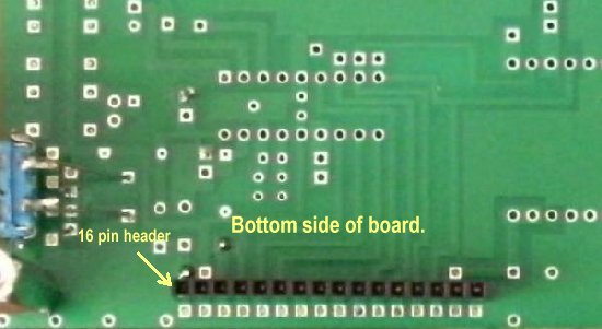
Install and solder the 16 pin header for the LCD display cable to the bottom side of Board 1. Notice that it is in the inside row of 16 plated through holes. The outside row will have connections for the LCD display from the Arduino board. Solder one end pin and make sure the header is straight up and down. Reheat and straighten if necessary. Solder the other end making sure the header is up against the board. Then solder the other pins. |
|
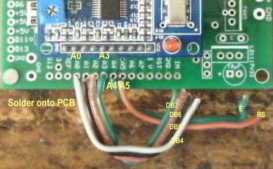
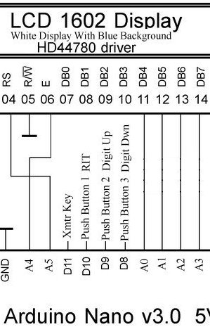
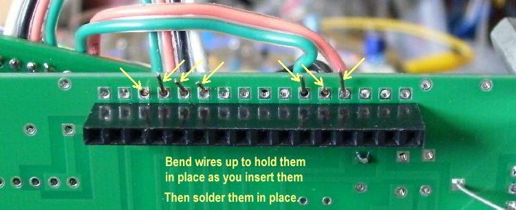
Above is the schematic for the first wires to be connected to Board 1. The connections for the four wire cable (2-1/2" long) are the following: The connections for the two wire cable (2-1/2" long) and Ground wire (1-3/4" long) are the following: Bend the bare wires forward when you get them inserted to hold them in place. Then solder them and clip the extra bare wire length. |
|
After soldering the wires and double checking the connections, mount the Arduino board onto Board 1 using the three 4-40 nuts left over from installing the screws and double nuts onto the Arduino board. 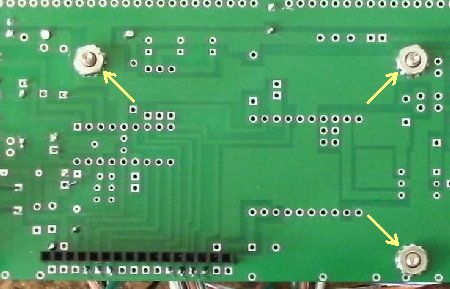 Be sure the double nuts are tight against the bottom of the Arduino board before laying on Board 1 and tightening it down to Board 1. Connect the wires for the switches, the rotary encoder, and the +5 Volts. Switch connections: ____D10 to Switch 1 Rotary connections: ____D2 to ENC1 +5 Volt connection:: ____+5V (left connection at 7805) to +5V on Board 1 |
|
DDS Out, Key, 12 Volt, and Ground Connections:
|
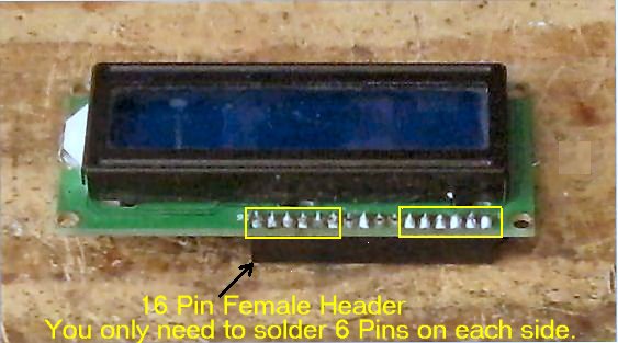
Install 16 Pin Female Header onto the LCD Display____1 - 16 Pin Female Header Solder one end pin and make sure the header is straight up and down, if not, reheat the connection and straighten the header, then solder the rest of the pins as shown below. It is not necessary to solder the middle four pins. |
|
|
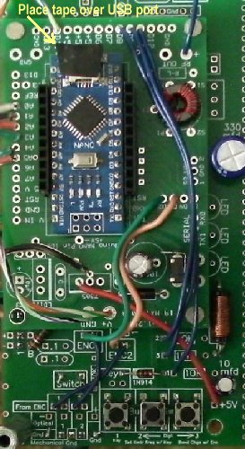
Place a small piece of tape over the USB port on the Nano. The insures that it will not short out a soldered hole on the DDS module around the Blue Trimmer. Install the Nano on the Arduino board with the USB port over the box that says USB as shown below. Be careful to install it correctly on the pins below. Install the DDS Module over the Nano on the 10 pin headers with the Blue Trimmer over the USB port on the Nano. |
|
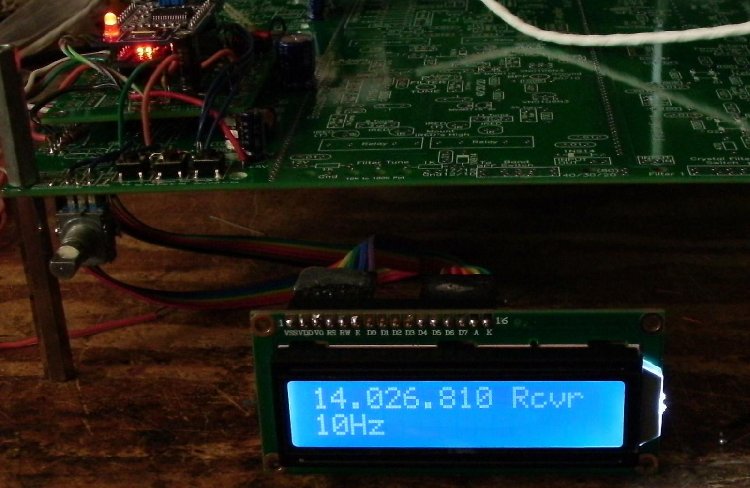
The display should read a frequency and show the digit the encoder moves. Switches 2 and 3 will move the digit number, either left or right, that the encoder will tune, from 100kHz to 1Hz. Switch 1 is used for the RIT function and the encoder will move it in a negative or positive direction. To turn off RIT, push Button 1 again. Push the encoder to engage switch (connected to Switch 3) and the digit number will increase. To change bands, move the digit number to 100kHz and move to the band frequency desired. When the Key line is grounded, the Rcvr (top right of display) will change to Xmit, showing that the offset has been eliminated from the output frequency. After testing, disconnect the cable from Board 1 and set the LCD aside. You will be mounting it with plastic ties right under Board 1 when you get to Mounting/Testing Board 1 |
|
If you built this as the first part of the Ham Radio BLT and need to continue to building the VFO Amplifiers and the rest of the receiver, click on the following link: Continue to Ham Radio Blue Lightning Transceiver - DDS VFO Amplifiers |
Send E-Mail || Amateur Radio Receivers || Back to Blue Lightning Transceiver