|
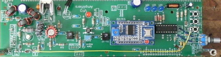
Section 1 of Board 1 is shown above. The DDS VFO is on the right, the VFO amplifiers in the middle with one IR Receiver (black, bent over) controlled MOSFET amplifier, one 2N5109 amplifier, and the T/R switch on the left. The 5V regulator (tab heatsink) with capacitors for the DDS is on the top left. |
|
LCD output is at the bottom center of the board. Orange wire connects Key of DDS to Key of T/R switch. The extra LCD output pins underneath the one soldered is used for the optional Arduino Board to connect to the LCD. |
|
This DDS VFO is a simplified PIC-EL. The idea for a simplified PIC-EL originated with VK5TM. The original configuration is at his website: http://www.vk5tm.com/dds/dds.php An excellent website for many good ideas on working with DDS projects. I worked on the code for several months and got a Transmit Function to work. Grounding an output of a PIC16F628 pin eliminates the offset in the calculation of the DDS word and outputs the exact receive frequency for output to a transmitter. The Transmit Function makes the circuitry for the transmitter simpler. It eliminates a mixer, filter, and a couple of amplifiers. The output of the DDS goes directly to an amplifier that drives the output device of the transmitter. This lowers the cost and the parts count of the transmitter considerably. The BLT can drive any QRP transmitter with an output of 200mW from the VFO amplifiers. QRP transmitters that need less than 200mW drive will use a 3dB or 6dB resistive pad between the BLT and the transmitter. 
Fixed Attenuator Calculator Online:
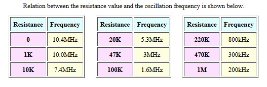
Will calculate any impedance and any desired attenuation. The PIC used in this simplified PIC-EL will also work in the PIC-EL boards with the modification of disconnecting the transistor driving the speaker output. That switch is then used for a KEY output that is the transmit function of the DDS VFO, eliminating the offset from the output of the DDS. The 1st and 2nd generation PIC-EL boards work extremely well with this transceiver as having an outboard DDS VFO lowers the birdies and noise of the DDS from the receiver, resulting in a very clean receiver output. I have not tested the PIC-EL III boards, but they should work. This board is reasonably priced and is available from Craig Johnson, AA0ZZ at http://cbjohn.com The DDS VFO on the receiver board is not that objectionable. Birdies are minimal and is very convenient to have on the receiver. Birdie reduction techniques have been used to reduce them considerably. The band noise on the lower bands covers almost all of the remaining birdies. On the higher bands, above 15 Meters, birdies have not caused problems receiving signals except at one or two frequencies. The problem is most prevalent on 10 Meters, but the band is useable. PIC16F628-20I/P, PIC16F628A and OscillatorThe PIC used is a 16F628-20I/P or 16F628A. The oscillator used with the 20I/P is the internal oscillator with the frequency controlled by a resistor to ground on Pin 16. With a zero ohm resistor (bare wire lead below shown with yellow arrow), the oscillator runs at ~10.4 MHz, which allows both a 24 step mechanical encoder or a 128 step optical encoder to be used. 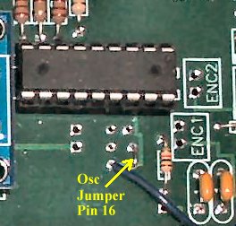 |
|
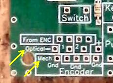
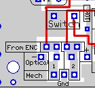
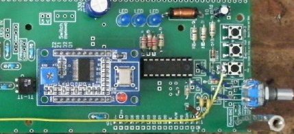
The 16F628A uses its internal 4MHz oscillator and works equally as well as the 16F628-20I/P. The 16F628A does not have the resistor setting oscillator option. The internal oscillator is used as it has the lowest emissions outside of the PIC for quiet operation with the receiver. The crystal oscillator was hard to isolate from the receiver board. Pads were placed on the board in case a crystal oscillator is preferred, including pads for the two capacitors used with the crystal. The board has provisions for either a optical or mechanical encoder to be connected. See picture below, First production boards on the left and later production boards on the right.
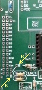
Notice on the Optical Encoder the negative connection (-) and positive connections (+) on either side of the 1 and 2 connections. Notice on the Mechanical (Mech) Encoder that the middle connections have a ground in the middle between 1 and 2, which is the most common pinout of Mechanical Encoders. The Switch box is for connections to the Mechanical Encoder shaft push button switch. It is located back from the encoder so that the wires to the switch help hold the encoder upright if the shaft is mounted horizontal toward the front of the board. The wires can be made very sturdy if #14 wire is used or short lengths soldered to #24 wire used to make the connections. See the instructions. The Switch box is connected to PB2. PB2 is pushed along with the Morse Code Key dit or dah lever (with iambic) or down (straight key) to set the transmit frequency. Key is connected to PB1. This makes it quicker/easier to set the transmit frequency. Pushing the encoder knob and making a dit or dah with the Morse Key sets the transmit frequency. PB2 also moves the cursor to the left one decade. DDS ModuleThe DDS module is the EBay AD9851 or AD9850 board from China. An inexpensive module with the oscillator, power supply filtering and input/output pins on one plug in board. The AD9850 or AD5851 board can be used with a simple change in the code. The AD9851 is used for better performance on the higher bands and is equivalent to the DS60 board used on the PIC-EL. However, the AD9851 module is hard to find. 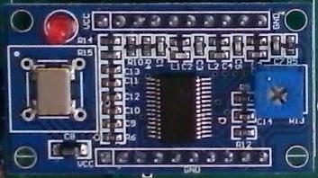 DDS VFOs OutboardA lot of other DDS VFOs can be used instead of the onboard DDS VFO. Provisions have been made to tie in other outboard DDS VFOs. More information is available at DDS VFOs with Transmit Function. If you have a DDS VFO already, you can use it with the BLT and save on cost by not ordering the BLT onboard DDS VFO. The outboard DDS VFO output is tied to the DDS IN box and the 5V power can be tied to the 5V box. If you built the onboard DDS VFO as shown in the picture, remove the .01 cap directly beneath the MOSFET (yellow arrow) to isolate the output from the onboard DDS VFO. 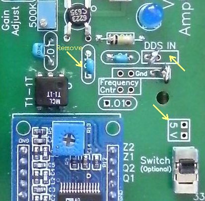 The MOSFET amplifier gain adjust has worked for all the outboard DDS VFOs I have bought, with or without an additional amplifier (MMIC amp) after the DDS Module. LCD ModuleThe LCD is a white on blue 16x2 HD44780 display. The background lighting is slightly different than other 16x2 displays with full 12V (no resistor) powering the backlight. If you use other 16x2 displays, check its specification sheet to make sure how they recommend powering the backlight (most require a low value resistor). Notice in the PCB image below, the V+ (the blue backlight supply pin), the second pin from the top, goes directly to the +5 bus. Contrast control is set with a 1K or 1.2K resistor which has worked with all the Blue displays I have used. It goes between the two holes marked "B" for "Brightness". |
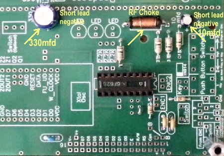
 12 Volt bus Cleaning |
|
One large RF choke (100uH), to prevent a voltage drop, and two electrolytic capacitors (330mfd and 10mfd) are used to keep birdies and noise off the 12 Volt lines. The combination was effective. |
|
The official name for this software is PicElGen - Signal Generator (VFO) with Direct Digital Synthesis. The initial version was written by Curtis W. Preuss, WB2V. Converted to MPASM by Bruce Stough, AA0ED, and then modified by Craig Johnson, AA0ZZ, for the PIC Elmer project. Bob Okas, W3CD, C. Beck Ewing, and T. Mowles, VK5TM also made significant contributions. Three versions of the PicEL project were developed and sold. Currently, the third version is at Craig Johnson's website at http://cbjohn.com, the PIC-EL lll. I ordered and built Version l and 2, and they worked great. Then I found a version that had been simplified, not having the programming section on it, developed by VK5TM. I built the simplified version and with John McDonough, WB8RCR's PIC Elmer 160 course, learned how to write, modify, and learn the PIC programming code. The Elmer 160 is an online introductory course for the PIC micro controller from Microchip. https://amqrp.org/elmer160. The lessons are at https://amqrp.org/elmer160/lessons. It is well worth checking out.I modified the code so that the offset could be eliminated for a transmit function: be able to key the DDS VFO and have the receive frequency transmitted. The transmit frequency is set by Pushbutton 3 and taping the key. The receive frequency can be changed at will and the transmit frequency will remain set at the intended frequency set by PB3 and the tap of the key. Whenever the key is used the DDS sends the transmit frequency and activates the T/R switch to send the signal to the transmitter. Full QSK is realized.
Software Utilities1. Selection of the DDSAt the very first of the code, the type of DDS can be chosen, using either the AD5850 or the AD5851. |
|
A semicolon in front of #define (;#define) turns it off and other one is used. 2. Setting up the Bands and Offset frequencyThe code uses a Band table to setup the bands and the offset is set for each band in the IF table. This makes it very versatile so that the receiver can be set up for different crystal filter frequencies or for two different crystal filter frequencies (since there are two crystal filters). Band TablesThe following three tables are the Band Tables. There is no need to modify these tables unless you want to add another band. The 6 meter band has a colon in front of it and it needs to be removed if you modify the receiver to use 6 meters. All the follwing tables need to be modified if one is changed. The one that is of most interest is the IF table where the offset is changed when the crystal filters are modified from the stock 3.547Mhz crystals in crystal filters shipped with the kit. Note that in all the tables that the "Data is frequency, in Hz, expressed in hexadecimal and is stored LSB first". Instructions on how to do this is in "Modifications for other Crystal Filters" below. |

 >
>
Modifications for other Crystal Filters |
 /div>
/div>
Step OneThe first thing is to install the new crystals into the receiver Crystal Filters with the capacitors one wants to use in the filter. Then the receiver is turned on and the DDS signal generator is selected, Band 11 (no offset), that begins at 200kHz. The DDS is moved in frequency to the frequency of the crystals in the filter until the S-Meter is peaked at the strongest signal level. This is your offset frequency for that crystal filter. To illustrate this with the stock crystal filter, 3.547Mhz, use the DDS signal generator, Band 11, and tune it to 3.546 Mhz and you will find that the signal peaks at that frequency for the offset needed and is already in the IF offset table. Step TwoSecond thing is go to Signed binary converter - Decimal to Hexadecimal converterClick on "Convert" Use the "Hex signed 2's complement" number. Note in the instructions that the LSB (Least Significant Byte) goes in the table first. The 90 goes in the left most slot, then 1B, 36, and with no more numbers, the following slot is 00. Each byte is 2 numbers. If you go two at a time and run into one number, add a zero to it, and then follow with two more zeros if necessary. Don't forget to put in the commas, leave them out and you will get an error during the build of the program amd the hex code will not be generated. |
|
If you are going to subtract the offset, put a minus sign in front of the decimal number (in Hz, i.e., -3456000) you put in the top box. Click on "Convert", use the "Hex signed 2's complement" number. Again, note in the instructions that the LSB (Least Significant Byte) goes in the table first. The 70 goes in the left most slot, then E4, C9, and then FF. |
|
The reason for the negative offsets is that the higher the frequency you go with the DDS module, more spurious outputs are generated. So the higher bands use a negative offset to keep them as clean as possible. It helps to use high frequency crystal filters with the higher bands, especially 12, 10, and 6 meters, to keep the spurious outputs low. The disadvantage to higher frequency crystal filters is the difficulty of getting narrow bandwidths, but the higher bands are not as crowded as 20 meters and below, so it is not that much of an issue. Crystal filters as high as 20 MHz help a lot. In fact, getting to 6 meters with a AD9851 requires a high frequency crystal frequency. The one with the kit uses one 26.640 MHz crystal for low loss and a reasonable IF frequency.. |
|
MPLAB Xpress Cloud-Based IDE is an online development environment that contains the most popular features of their award-winning MPLAB X IDE. It is simplified and distilled application of its desktop-based program and is easy and free to use. You get to download your generated .hex codes and use them with any program and burner to make your chips. Ebay has some very inexpensive programmers to purchase. Click on the link above and sign up to use it. Click on Import Project. Hit the Browse button and it will go to your computer. Go to the 'BLT CDROM Folder' on the CDROM. Open the CDROM in Windows Explorer and open the folder 'BLT CDROM Folder'. Then open the PICEL folder. A .zip file can be loaded in the Import Project as it asks. The file is Blue_transmit_PICEL.zip. It loads every file and configuration you need to begin to study and modify the program as you wish. In the Project box you will see the project name Blue_transmit_PICEL and listed Source Files: PICELGen_2_4a_offset_transmit.asm and p16f628.inc In the Dashboard below you will see several things listed. Device - PIC16F628, Complier Toolchain - MPASMWIN (5.77), and Debug Tool - PICkit3. There will be other things in the box, too. The .asm file will be listed and shown in the larger box to the right of the Project box. Above this you will see a Hammer icon, click on the Hammer icon and the Output box at the bottom will show up and should eventually show "Build Successful". At this point everything is ready to make changes to the IF Table for changes to the Crystal Filter modifications. Click the x on the Output name so you can see the full .asm file. You are now ready to scroll down to line number 1111 and make changes to the IF table. Programming the ChipAfter the changes to the IF table have been made, click on the hammer icon and make sure the build is "Successful". If not, recheck what you have done and find your mistake(s). Then click on the bar on the right side of the Hammer icon with a brush. A menu will drop down that says "Clean for Build and Export". Click that menu item and a box will open with the .hex file ready to open in Notepad or "Save File". Save the file. Your browser may put it in its Download File directory, or if you have gone into Preferences, you have the option to put it where you choose. Check the choose option and save it to a directory in My Documents called "MPLAB Express hex files". The .hex file is ready for programming the chip. I use a free program from Microchip, MPLAB IPE, (Integrated Programming Environment), in which the hex file is loaded and any number of Microchip programmers can be used. I use PICKit 3. They have a PICKit 4 now. Pic progammers are available on Ebay at very reasonable prices and will work with the .hex file downloaded from MPLAB Express. With the .hex file, you can use any PIC programmer. After programming, make sure you put it in the socket correctly, and check operation. |
DDS VFO InstructionsPushbutton OperationStarting at the rotary encoder, the switches are labeled 1, 2, and 3. Operation when Listening or QSOingWhen the receiver is first turned on, 40 Meters will be the displayed band. After the first turn on, the last band/frequency will be saved and loaded on start up. To change bands, hold down Button 3 (right button) and turn the encoder (within one second) to the band you want. You will be at the start of the band - XX.000 The default digit will be the .01 digit, and tuning will be fairly slow through the band. If you want to scan the band quickly to find signals, push button 2 (middle button or encoder switch) and it will move to the .1 digit for quick tuning through the band. When you find a signal you wish to tune in, push button 3 (right button) to move the cursor to the .01 digit and you can tune in the signal precisely. If you wish to transmit on this frequency, push the encoder knob/switch, and tap your key. You will see that the Band number will now be displayed on the bottom line of the display and will show your Transmit frequency. Your transmit frequency will remain the same until you hit the encoder knob/switch, and hit your key at a different frequency. Whenever either Digit button (PB2 or PB3) is held down, it will start to scroll through the digits in the direction is in intented to go. By using this feature, you can go to the digit you want with the knob switch (connected to Button 2) without having to use one of the buttons. You can set the Transmit frequency by pushing the encoder knob switch and the key, and then scroll to the digit you want by pushing the encoder knob switch and let it scroll through the digits to the one you want. The only time you need to use a button is for band changing, when you Press Button 3 , within one second, turn the knob to the band you want. Once your transmit frequency is set, you have RIT and can move your receive frequency anywhere you like - transmit frequency will remain the same. When you set your Transmit frequency, Rcvr will remain on the display. When you transmit, Xmtr will show on the display with the transmit frequency, even when returning to receive, until the encoder is moved slightly, at least 1Hz, or the encoder knob is pushed. The receive frequency will remain the same even though the transmit frequency will be shown during the QSO, unless you RIT and the new receive frequency will be shown until you transmit again. If you finish your CQ or QSO and move to a different frequency and transmit without setting the new transmit frequency first, your old transmit frequency will show on the display. Push Button 2 (or push encoder switch/knob), and tap your key to set the new transmit frequency. PB1Used with PB2 to set Transmit FrequencyPB1 is used for the transmit function. When grounded, it removes the offset and outputs the correct frequency used for transmitting. The change to transmit frequency and changing back to the receive frequency with the offset is very fast. Up to 40 wpm has been no problem. When you transmit, the Transmit Frequency and Xmtr will remain on the display. The receive frequency will stay the same. If you move the Rotary Encoder, the Receive Frequency and Rcvr will be displayed. Pressing PB1 (Key/keyer) and PB2 (or encoder switch) at the same time sets the transmit frequency. After setting the transmit frequency, you are free to turn the Rotary Encoder to any receive frequency you desire. For working DX up1, you move the frequency up one 1kHz, set the transmit frequency and then move back to the DX station frequency. PB2Cursor to LeftMomentary depression moves cursor to the left one decade position. The cursor will wrap from highest decade to 1 Hz decade. Holding down for one second will start automatic movement of cursor to left every 1/8 second. CALIBRATE MODE is entered if PB_2 is pressed during power-on. See Calibrate Mode below for instructions for calibrating. PB3Cursor to RightMomentary depression moves cursor to the right one decade position. The cursor will wrap from the 1 Hz decade to the highest decade. Holding down for one second will start automatic movement of cursor to right every 1/8 second. Band ChangeDepressing PB3 and moving encoder before one second will enter band change mode. Moving the encoder will cycle through all the bands configured until releasing PB3 which will select last band displayed. Set Transmit FrequencyPB1 is connected to your key/keyer. You press PB2, or encoder switch (knob) and hit the key, the transmit frequency is set to the frequency on the display. PB2 is connected to the switch on the mechanical encoder for quick setting of the transmit frequency. The transmit frequency will not be transmitted or displayed when you set it. If you want to check the transmit frequency, send one dot (will be transmitted) and Xmtr with the transmit frequency will be displayed. You can move the receive frequency as desired (for RIT function); the transmit frequency will remain the same. If you finish your QSO and move to another one at a different frequency, remember to reset your transmit frequency. Press PB2 (or encoder knob/switch) and hit the Key to set the new frequency. If you forget and see that you are transmitting at the old frequency, press PB2 (or encoder knob/switch) and hit the key to set the correct transmit frequency. Key ConnectionThe "Key" box on the board at the T/R switch is where a key, either hand key or an iambic keyer, is connected to send CW. This "Key" connection is grounded to activate the transmit function, activate the T/R switch, and send the signal to the transmitter. A diode, the anode connected to the output of the PIC to PB1 is used to isolate it from the keying line. Also, a diode (anode side) is connected to the PNP switch of the T/R switch. Then both cathodes are connected together for the connection to the key/keyer, which grounds the two cathode diode connections when keyed. The KEY connection is at the T/R switch labeled "Key" at the edge of the board. The key connection from your bug, iambic key, straight key, or any other key should be connected here. Tuning Range of the DDS VFOThe tuning range of the DDS VFO is set by tables in the PIC code. It is divided into the Amateur Radio Bands 160, 80, 60, 40, 30, 20, 17, 15, 12, 10, one general coverage band (0 to 40 MHz), and one signal generator band that ranges from 200 kHz to 40 MHz which has no offset programmed - the frequency shown is what is generated and received. 160 is not available, but was left if one wanted to add a Bandpass filter for it. 80 can be received by adding additional 400pf varicaps to the 40, 30, 20 bandpass filter. The bands are labeled on the readout 1 to 12, starting with 160, Band 1, to the signal generator band, Band 12. Any crystal filter and offset can be used with any band, as the they can be set individually in the Band tables and the IF offset table. See Program Code. Calibration ModeIf PB2 is depressed during power-on, Calibration mode is displayed. The display shows 10,000,000 CAL and a 10 MHz signal is generated. The output should be monitored with a Frequency Counter, or other means, for correct frequency. While holding PB2, the encoder is used to adjust output frequency to 10 MHz. Once output frequency is correct, release PB2 and turn encoder. Normal operation then starts. It is not necessary to hold PB2 if the encoder is not moved allowing entering calibrate mode and waiting for thermal stabalization before calibrating. |
Send E-Mail || Amateur Radio Receivers || Blue Lightning Transceiver
Last Update: 8/16/2021
Web Author: David White, WN5Y