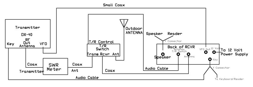
|
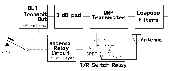
In the BLT, commercial IRED emitters can used in the IRED(T) footprints in the Bandpass Filters on Board 1. This commercial pair of emitter/receiver and optical cable can to used to automatically switch the lowpass filters of the transmitter. They are used with the Bandpass Filter potentiometer to switch the lowpass filters used in the transmitter to automatically switch the filters in tandem.
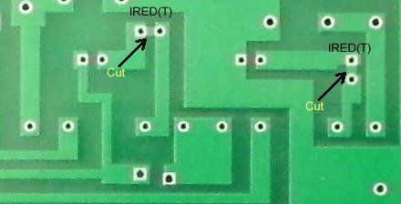
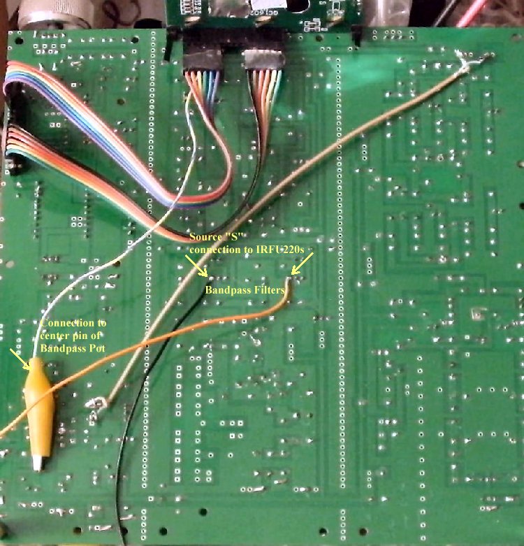
To install the IRED(T), there is a jumper trace in the footprint for the IREDs. That needs to be cut underneath the board and checked with a VOM to be sure there is no continuity.
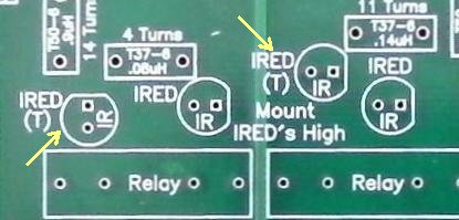
The short lead on the Blue Emitter goes to the flat of the footprint. This should orient the left IRED(T) toward the left of the PCB.
The right Blue Emitter will need to be turned counter clockwise a quarter turn after soldering to be pointed to the left of the PCB.
The optical emitters (Blue color) are pointed to the left hand side of the PCB soldered in the footprint. They come on with the selection of the Bandpass Filter.
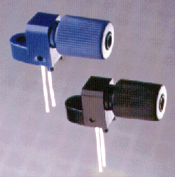
The following Optical Fiber kit is used:
Commercial Pairs w/1000µm Optical Fiber
Commercial Matched Pair Receiver/Detector
Blue - IRED Emitter || Black - Phototransistor Receiver
This pair of emitter/receiver and optic fiber is called the Experimenter's Kit IF-E10 in the Fiber Optics Kit section of Industrial Fiber Optics, Experimenter's Kit IF E10 web site. It contains a matched pair emitter/detector as pictured above and 1 meter of 1000µm optical fiber.
Two kits are needed to build this switcher.
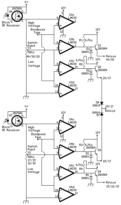
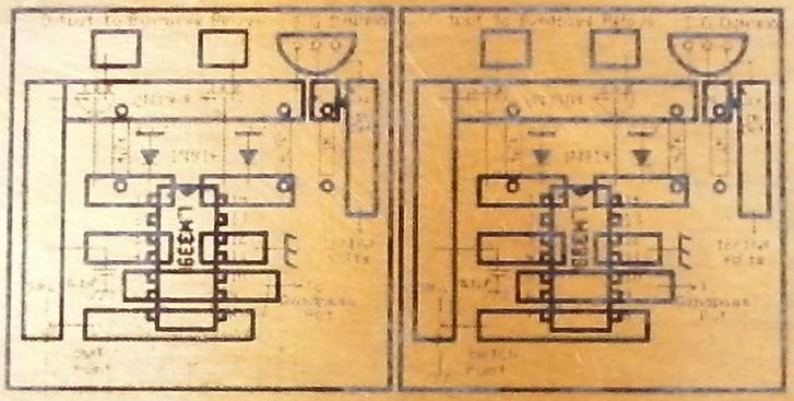
Lowpass Filter Switches
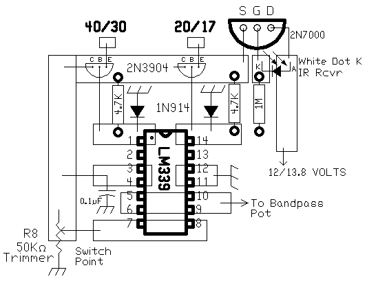
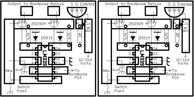
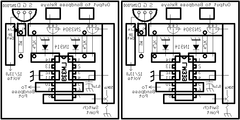
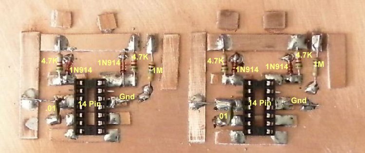
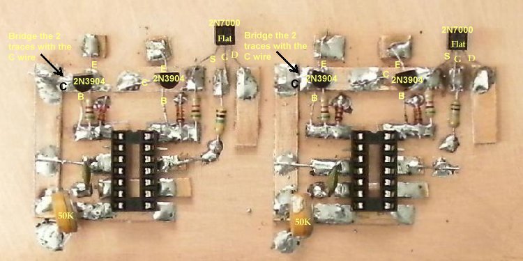
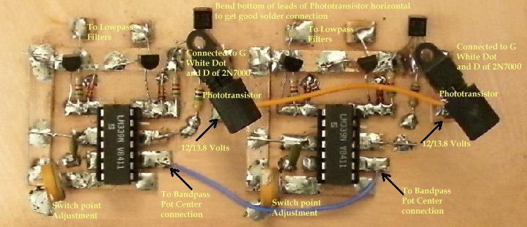
The schematic of the Lowpass filter relay switches is below. It comes from the "IC OP-AMP Cookbook, by Walter G. Jung, 1983, pg. 337", a staircase window comparator. It is modified to have two windows. As shown below it has a high voltage and a low voltage window with the switch point determined by a 50K potentiometer.
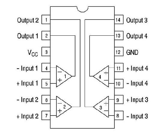
The operation works from the fact that when the inverting terminal is greater than the noninverting terminal, the output swings from Vcc to ground and the output gets turned on. This also depends on whether the output is a transistor output or logic output, which operate opposite of each other depending on how they are hooked up. The transistor output brings the output to ground and the logic output goes to Vcc. The LM339/LM393 is transistor output and the LM324 (single supply op amp) is logic output.
Each of the Bandpass filters use two lowpass filters to filter the output of the transmitter. The 40/30/20 Meter Bandpass filter uses a 40/30 Meter lowpass filter and a 20 Meter lowpass filter. The 17/15/12/10 Meter Bandpass filter uses a 17 Meter lowpass filter and a 15/12/10 lowpass filter.
Other variations are a 17/15 Meter lowpass filter and a 12/10 lowpass filter. The 20 and 17 meter lowpass filters can be combined or separated.
The LM339 comparator has an open collector output. The section of the LM339 that is off has 12 volts at the output, turning on the transistor and the lowpass filter relays it is connected to. When the section is turned on, it brings the output voltage to zero and turns off the relays.
If you use different op amps, which will work, they may have a 12 output when turned on, which is the opposite of the action of the LM339. An example is the single supply LM324, which I used with my first prototype.
The high voltage portion of the 40/30/20 Bandpass filter switches on the 40/30 lowpass filter and the low voltage portion switches on the 20/17 lowpass filter.
The high voltage portion of the 17/15/12/10 Bandpass filter switches on the 20/17 lowpass filter and the low voltage portion switches on the 15/12/10 lowpass filter.
The reason for the 50K pot instead of fixed resistors makes it useful for different Bandpass filter designs with different coil inductances, which will move where the bands are on the Bandpass pot, especially when 80 meters and 6 meters are used.
There are designs that use fewer turns on the 40/30/20 Bandpass filter that would require a different switch point. The 50K pot leaves it open to be used on any varicap tuned Bandpass filter.
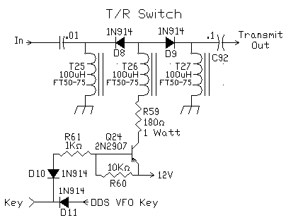
In the following schematic, there are two connections to a 20/17 Lowpass filter and they are isolated from each other with 1N914 diodes. This is not necessary with the op amp inputs since they are high impedance and are off when not used.
|