To learn about the BFO and Amplifier, read the
Circuit Details - BFO/Amplifier
before building this section.
To learn about the Product Detector, read the
Circuit Details - Product Detector
before building this section.
|
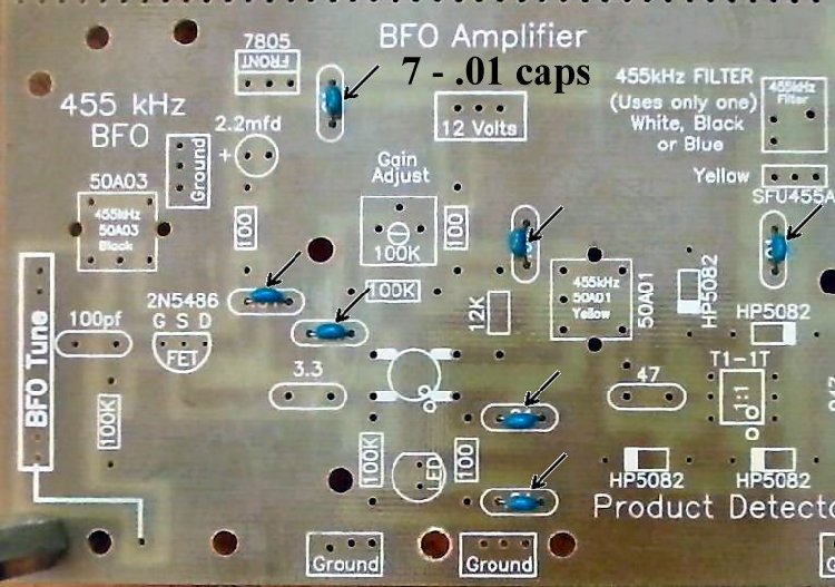
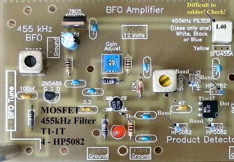
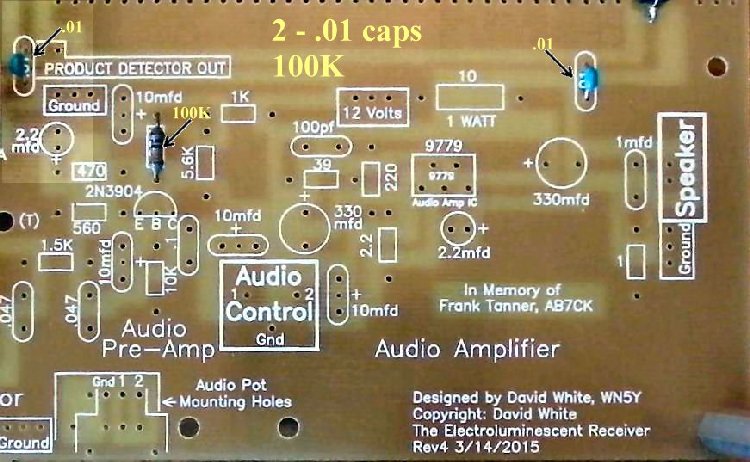
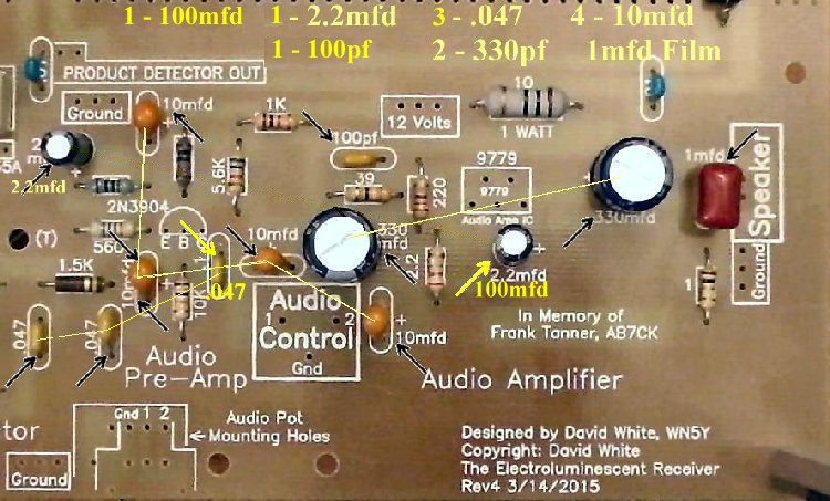
Insert all the components that have their values inside the footprint. They are the following: ____7 - .01 capacitors (Bag 3) |
|
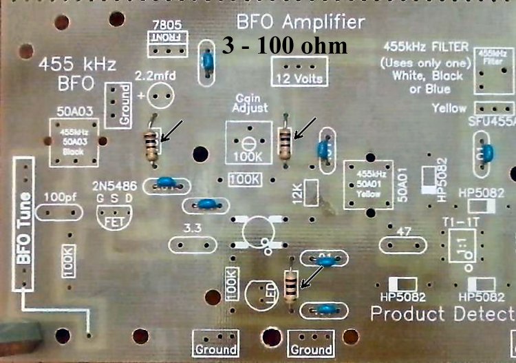
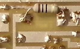
Solder ____3 - 100 ohm resistors (brown, black, brown) (Bag 3) Be careful, rectangle footprints only, there is a 100pf capacitor in the area. |
|
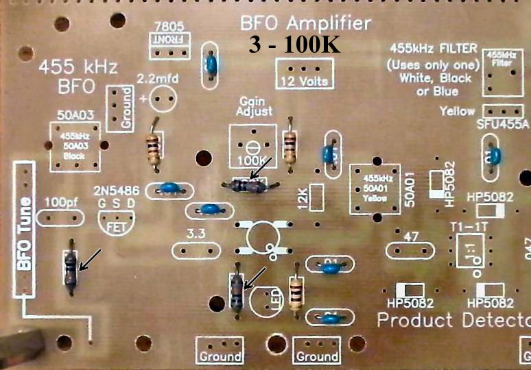
Solder ____3 - 100K resistors (brown, black, yellow) (Bag 3) |
|
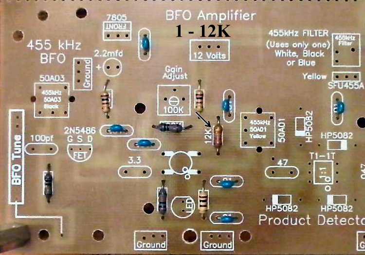
Solder Resistors:____1 - 12K (Bag 4), Located above the MOSFET on the right side. |
|
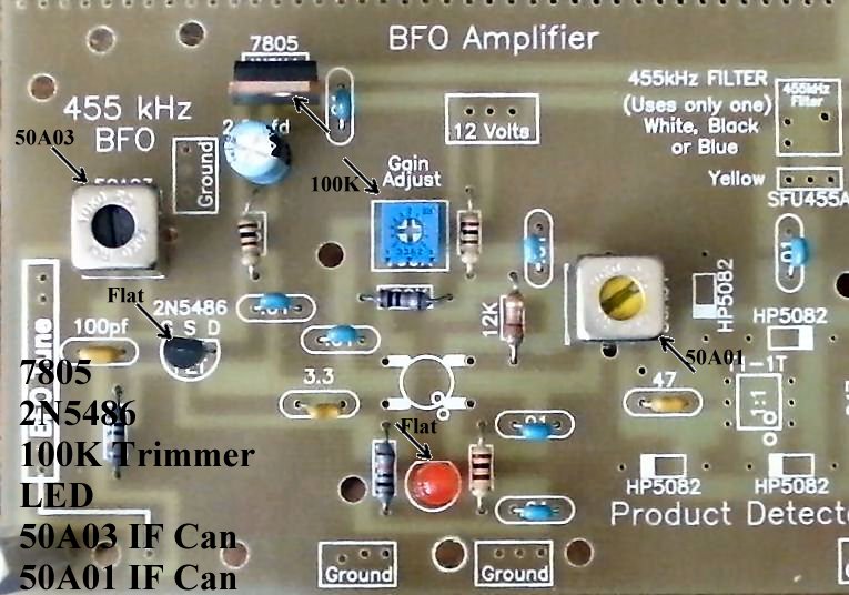
Solder Other Parts:____1 - 50A03 455KHz IF can, Black core (Bag 6), Located below the text "455 kHz BFO". After inserting into the board, touch the soldering iron to the IF can pins first, and make sure the pin is accepting solder before flowing solder onto the PCB. |
|
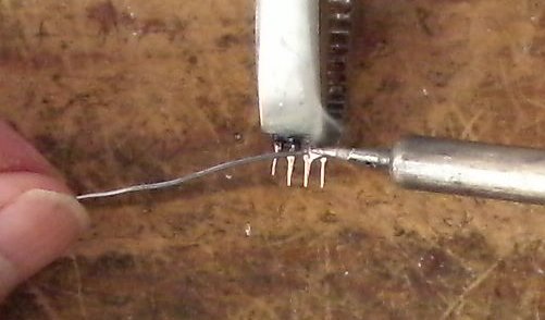
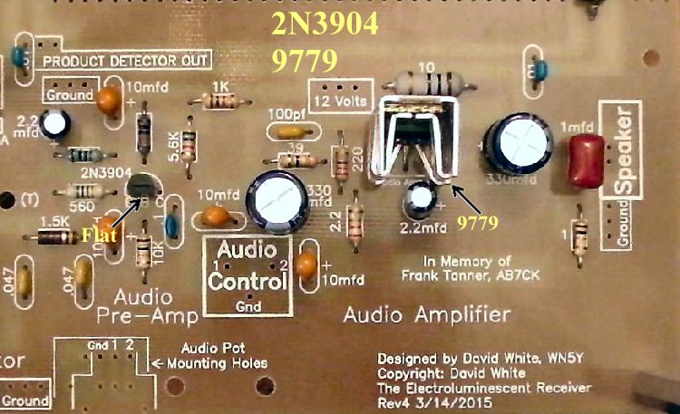
Solder ____1 - MOSFET (Bag 2), (Picture) static sensitive part, touch a ground wire before taking it out of the bag, notice the dot on MOSFET (may be difficult to see, hold at an angle to a light source and you can see the shadow of the dot), the dot is located to the left of the second line of the text on the MOSFET. Note: Tin all the leads on the transformer as the pads they solder to are small. This will make a solid solder joint. Wipe the excess solder to the top of the pin so it will fit in the holes. |
|
____1 - L40 B2 455KHz Filter (Bag 6), White color, another part with fragile pins, do not bend the pins when mounting/soldering the part to the PCB. Tin the leads with solder to get a good solder joint on the PCB. The 455 kHz filter can be a difficult part to solder, double check to make sure the pins are soldered to the pads. Use a magnifying glass and touch the pins with a small screwdriver to make sure they do not move. |
|
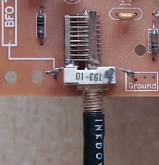
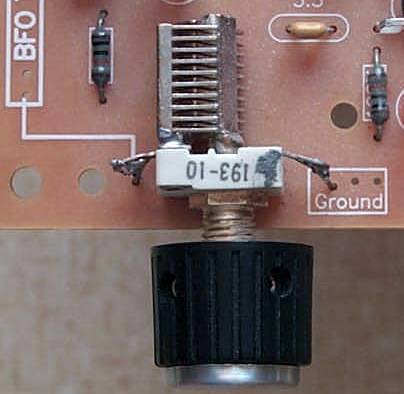
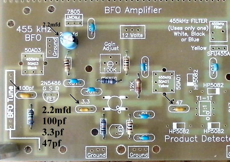
Solder BFO CapacitorFor those using Board 2 dated 2000, click here (BFO Capacitor Mounting) for instructions.  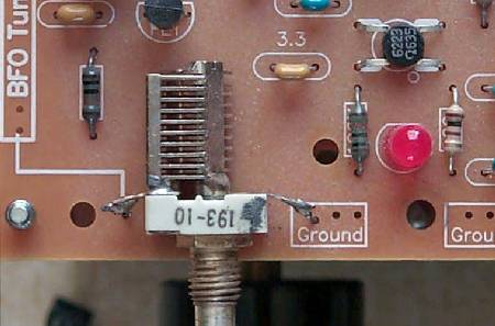 ____35pf small panel mount capacitor (Bag 1), with the numbers "193-10" on top, solder a 1 1/2" bare wire going down on each solder lug. 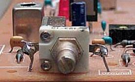 ____Check the capacitor for a firm mounting before clipping the wires. If loose, reheat the solder on the loose wire and retighten.
|
|
Approximate time to complete 0:45 - Picture
Insert all the components that have their values inside the footprint. They are the following:
____2 - .01 capacitors (Bag 3) |
|
Solder Resistors:
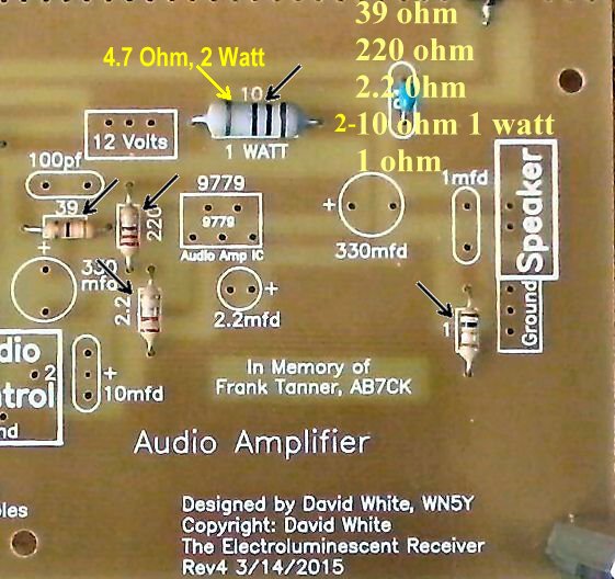
____1 - 1K (Bag 3), Located above the 5.6K resistor. If you are using Board 2, dated 2000, please click Audio Gain Modification ____1 - 560 ohm (Bag 5), Located above the 1.5K resistor in the 'Audio Pre-Amp'. 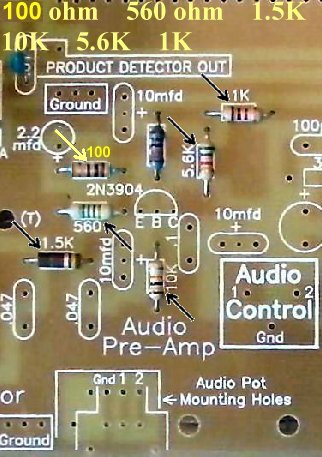 Solder ____1 - 39 ohm (Bag 6), Located above the 330mfd electrolytic. |
|
Solder |
|
Solder Audio Control PotentiometerIf you are using Board 2, dated 2000, click Installing the Audio Control Potentiometer
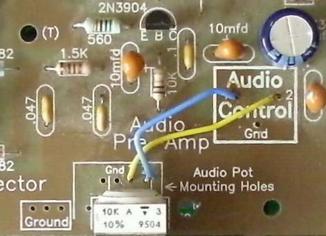
There is a place below and left of the Audio Control Square that has ten holes that will accommodate most PCB mount potentiometers. The pot supplied with the kit has five pins and matches the five holes in the forward part of the square. The pins are slipped through the holes and then soldered. Connection wires are run from the pins labeled "1", and "2" and run to the "Audio Control" square. The Grounds are connected through the ground plane. Wiring the Potentiometer |
|
____1 - 10K Potentiometer (Bag 6), A small white pot labeled 10K in the upper left hand corner on the top. ____Use a 1 1/2" jumper wire and connect the the hole labeled "1" to the hole in the "Audio Control" square labeled "2". ____Use a 1 1/2" jumper wire and connect the hole labeled "2" in the "Audio Control" square labeled "1". S-MeterWhen you click on the Pictures or links below, click the return button (Back) on the browser to return here.
 ____The resistors that are used at M1 and M2, to the left and above the S-Meter Square at the AGC Detector (Picture), are set up to use a 50uA meter. (Picture) You can use any meter with a value between 50uA to 250uA, by changing the M1 and M2 resistors. Values for different meters are given in the S-Meter page. Circuit theory is included to help you properly set up the meter any way you like. ____The S-Meter, if board mounted, is glued to the top or bottom of the board where the text "Audio Amplifier" and the "Designed by...." is located at the bottom right of the board. Silicon Rubber Sealant was used to secure the S-Meter on all the prototypes, and allows you to pull the meter off the board if you transfer the receiver to a case, where you will be mounting the S-Meter on a front panel. Picture ____Solder a wire from the + hole in the S-Meter square on the PCB to the + connection on the S-Meter.____Solder a wire from the - hole in the S-Meter square on the PCB to the - connection on the S-Meter. Picture |
Double Checking Your Work
____Place the PCB in front of a bright light. If you see light shining through any of the soldering holes, you missed a solder connection. If you have already tested Board 1, go to Mounting/Testing Board 2. |
Send E-Mail || Amateur Radio Receivers || Back to SWL Instructions for the Blue Lightning Transceiver