|
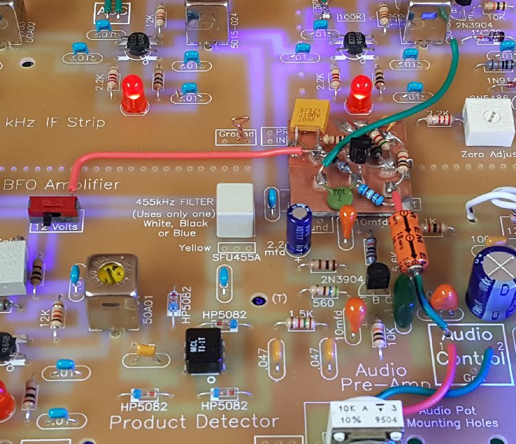
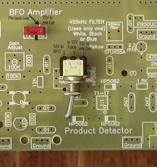
This AM detector comes from the article "Recent developments in circuits and techniques for high-frequency communication receivers", by Ulrich L. Rohde, KA2WEU/DJ2LR, Ham Radio, April 1980, page 20. Under the subtitle "linear detectors", Mr. Rohde explains the AM detector: "AM detectors are frequently required to have very low distortion and because of this, the IF level must be kept at a very high level. Because of gain distribution, this is not necessarily very desirable, and a feedback am detector as shown in fig. 8 is ideal." My note: This is the case with this receiver, the IF level going into the product detector is very low, -60dBm to -40dBm. To raise the level, the output from the 455 KHz filter is routed to the input of the BFO MOSFET amplifier. The 3.3pf cap is removed at the input to the BFO amplifier. Then the output of the BFO amplifier, at the 47pf cap, which is also removed, is routed to the input of this detector coupled with a .01 capacitor. Continuing with Mr. Rohde: "The output distortion is substantially less than one per cent up to a very high modulation percentages; it should be driven from an impedance of less than 200 ohms which can easily be provided by using an emitter follower." The following picture shows the implementation of the AM Detector on Board 2 including switching so that either AM or CW/SSB (product detector) can be selected. There is also a modification to the AGC circuit, adding the AGC amplifier to the AGC circuit. AGC Amplifier modification Please note that this picture does not show the 10mfd capacitor at the output. It is needed and shown in a picture below. |
|
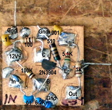
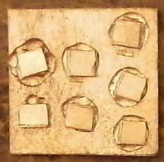
Shown below is the "dead bug" style of construction to build the AM Detector with a 1" by 1" PCB board.
|
| 1 | 2N3904 | NPN Transistor |
| 1 | 0.1 | capacitors |
| 1 | 0.01 | |
| 1 | 0.001 | |
| 1 | 10mfd | |
| 1 | 100 ohm | Resistors |
| 1 | 510 ohm | |
| 1 | 1K | |
| 1 | 5.1K | |
| 1 | 6.2K | |
| 1 | 100K | |
| 1 | Single sided PCB 1-1/8" by 1-1/8" |
Dead Bug const |
| 1 | 7 small PCB pads | glued with Super Glue |
Small pads are glued with Super Glue onto the board with the following layout. The Manhattan Layout Mirrored can be copied and printed to use for Blue Stick type of construction.
Resize mirrored layout Width 1" by Height 1.19" after loading into a graphic program (i.e., IrfanView, free graphic viewer on the Internet), print and stick on the pads, place glue on pads, turn over and stick on PCB.
|
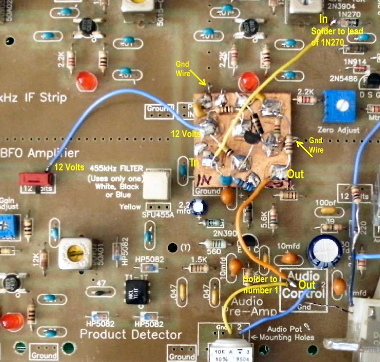
The AM Detector board is laid on Board 2 as shown below with ground wires as shown to hold it to the PCB and provide ground for the circuit. Note the 10mfd capacitor at the output. |
|
After a switch is mounted, attach three wires to the 12V, In, and a 10mfd capacitor (at the Out) to the places on the AM Detector board and wire them to the appropriate places as shown below. Remember, a 10mfd capacitor is placed between the output and to the audio input - not shown below - see picture. |
|
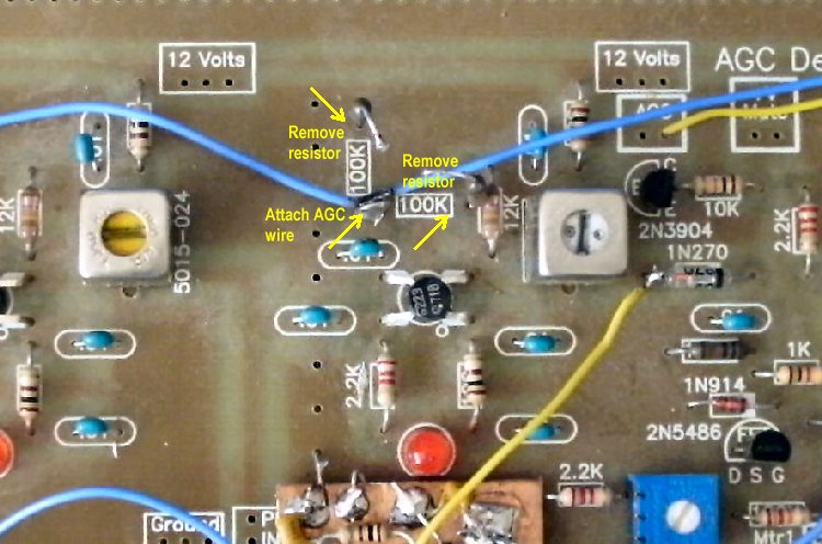
____In wire, 2-1/2" long goes to the right side of the 1N270 diode. Also note that the wires from the audio pot to the Audio Control box have been changed from what is shown in the picture. Number 1 from the audio pot goes to 2 in the Audio Control box, and Number 2 from the pot goes to 1 in the Audio Control box. See Wiring the Potentiometer. Back to Building Board 2, Section 3AGC ModificationAGC needs to be added to the AGC amplifier. It was noted that if the amplifier ran wide open that it would overload the AM Detector and distort the audio. The AGC still works fine with both CW/SSB and AM. |
|
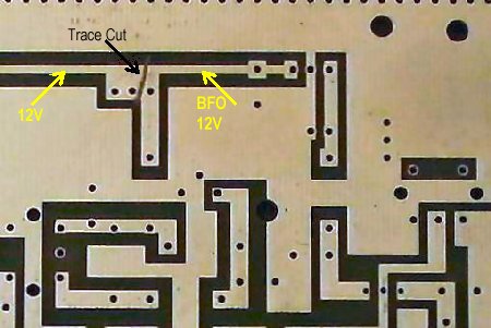
_____2 - 100K Gate 2 bias, AGC amplifier, remove the leads from the PCB as shown above, remove the resistors, or don't install.  |
|
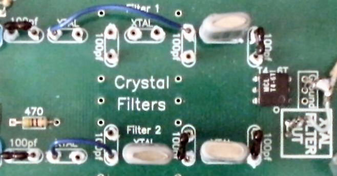
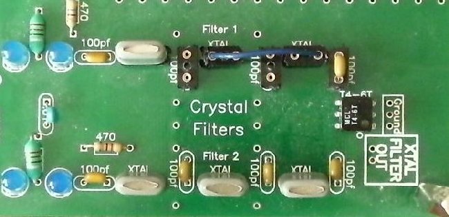
With AM detection, a wider bandwidth crystal filter is needed. A one 3.547 MHz crystal filter with two 100pf capacitors provides the bandwidth for AM and SSB listening. A little tighter bandwidth with a two crystal/100pf capacitor filter also works but seems to cut off the highs somewhat. The tighter bandwidth allows weaker stations to be received in some situations. The implementation of the filter is shown below. SIPs are installed in all the crystal and capacitor locations giving the ability to experiment with the filter. Black SIPs are now sent with the kit and #22 solid wire works well for the jumper wires. |
|
If you are building the kit solely for SWL purposes, you would not need to add the SIPs in either Filter 1 or Filter 2, just solder the parts into the holes. Filter 2 could have the SIPs in case you wanted to listen to the Ham bands and wanted a 3 crystal filter with higher value caps. For SSB, use the 39pf caps, for CW use 100pf. The SIPs are optional. Six 3.547 MHz crystals are provided with the kit so any filter you want can be made. Lower value capacitors widen the bandwidth and higher value capacitors are used for tight bandwidths. The same value capacitor is used throughout the filter. Ham Band and SWLFor a receiver built for both Ham Band and SWL, have one filter for AM and SSB reception and the other filter built for CW reception. |
|
The top filter is for AM and SSB reception using 2 100pf capacitors with one crystal. SIPs are used in all locations so that it can be modified to adapt to the builders desire. A jumper is installed after the first crystal to the 2nd 100pf capacitor. A #22 solid wire works well for the jumper. It can be modified from a one crystal filter to a two crystal filter by putting in one more 100pf and another crystal as shown in the filter for SWL reception above. The bottom filter is for CW reception for Ham radio using 100pf caps. Back to Crystal Filter Crystal Install |
DDS VFO Key is not connected to the T/R SwitchDo not install the Key wire loop. It is not used in the SWL version.
 Do not install the DDS VFO Key wire to the T/R switch. It is not used in the SWL version.
 |
|
Do not use the SIPs as shown in the Ham Radio picture. |
|
Low Distortion/High Dynamic Range Detector The detector provides both low distortion and very high dynamic range. It can cleanly demodulate AM signals, even with positive peak modulation in excess of 200 percent. An Improved Precision Full-wave AM Detector, by Rob Schenck, K2CU. "This circuit is a variation of the classic "Precision Half Wave Rectifier" as described in many op-amp application notes..." The Envelope Detector A mathematical analysis of the diode detector. Doug's Short Wave Radio Page Very good information on synchronous AM detection. Lots of excellent references. The Synchronous Oscillator, Designed by Vasil Uzunoglu |
Send E-Mail || Amateur Radio Receivers || Blue Lightning Transceiver || Back to Instructions for the Blue Lightning Transceiver