|
There are two types of LEDs available to enhance the visual impact of the receiver kit: Bright Red LEDs and Super Bright LEDs. It is important to know the difference so receiver performance will not be degraded.
Bright LEDs
The bright red/yellow LEDs can be used anywhere in the receiver. They have a forward voltage drop of 1.5 to 2.0 volts, which is the same voltage drop of the regular smoked red LEDs supplied with the kit.
The forward voltage drop of LEDs can be measured using the diode checker on any DVM. Placed into the diode checker, as indicated on the instrument, the reading should show between 1.5 to 2 volts on the DVM. If the LED leads are reversed there should be no reading on the DVM.
The MOSFET amplifiers and mixers are biased to use LEDs which have a forward voltage of between 1.5 to 2.0 volts. So any LED that shows a reading on a DVM diode checker of between 1.5 to 2.0 volts can be used anywhere in the receiver.
Super Bright LEDs
The Super Bright LEDs have a forward voltage drop of 3.5 to 4.5 volts. When Super Bright LEDs are inserted into the diode checker of a DVM, no voltage indication will occur no matter which way they are inserted. The reason is most DVMs use only two AA batteries (3 volts) and the high voltage drop of the LEDs (3.5 to 4.5 volts) will not allow a reading.
So the rule is the following: If you don't get a reading on a DVM when inserting an LED in the diode checker, then the LED is probably a super bright LED.
Super bright LEDs can only replace LEDs in the receiver that are used for switching indicators.
Super Bright LEDs can be used at the Bandpass Filter, Crystal Filter, and at the ELR 10.545 VFO relay.
The ELR 10.455 VFO relay LED is in series with the relay. A super bright LED at this location will not allow the relay to operate because of combined voltage drops in the 12 Volt circuit going to the relay.
Super Bright LEDs cannot be used at the crystal oscillator (indicating which crystal is active) because they will lower the output of the oscillator which greatly reduces the gain of the second mixer.
If a super bright LED is placed in the MOSFET mixers, the high forward voltage drop of the super bright will substantially lower the gain of the mixer. SB LEDs cannot be used in the 1st or 2nd mixer.
All the super bright LEDs come in a clear epoxy case. To tell the color of a super bright LED, use a 1K resistor in series with the anode (+) lead to a 12 volt power supply. The flat on the base or the short lead of the LED indicates the cathode (-) connection.
Connecting a power supply, no matter what the voltage, directly to an LED (without a resistor) will blow it instantly.
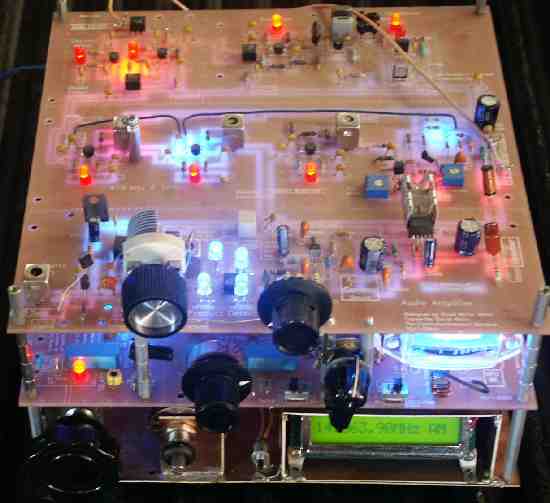
Board 2 is the best one to put on top. The reason is the LEDs on the IF strip will flash with the AGC action. The LEDs in the MOSFET amplifiers are visual indicators of the drain/source current of the MOSFETs, so any variation in the operating current of the device will vary the brightness of the LED.
The LEDs on the IF strip actually make a crude S-Meter. With no signal, the LEDs are at their brightest. The stronger the signal, the dimmer they will flash. The weaker the signal, the less effect on the LEDs.
To see the greatest contrast with this action, LEDs that have a smoked lens work best. The LEDs supplied with the kit show the flashing action about the best of any LEDs I have tried.
The stock red smoked LEDs work best on the top board. The reason is that putting any Super Brights on the top board will blind you and detract from the illumination of the board from the Super Brights on Board 1, mounted underneath Board 2.
Don't ever look at a Super Bright directly, or you might suffer spots in your vision, or temporary blindness. They are BRIGHT! Put them on the top board and you will tire very quickly of looking at the receiver.
The one exception is the BFO amplifier. This amplifier is usually run at a very low level of amplification. For least noise out of the speaker, running this amplifier with the LED just barely lit works best. You can put a Super Bright (my favorite was a blue) there, and look very cool with a dim blue glow.
I never got around to seeing the effect of putting Board 2 underneath Board 1. The look of flashing IF strip LEDs illuminating Board 1 might look pretty nice. So if you are so inclined, try it out.
Bottom Board
In all the prototypes, I put Board 1 underneath Board 2, illuminating Board 2 with the Super Brights on Board 1. It is much easier to put Super Brights on Board 1, because no circuit modifications are needed for the Super Brights in the switching locations.
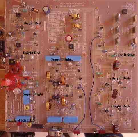
The image above shows the locations of the Super Brights and the Bright Reds used to max out the illumination of Board 1 with no circuit modifications.
My favorite band is 20 meters, so I wanted all blues to be lit when listening to 20 meters. For this effect, at the Bandpass Filter and Crystal Filter LEDs, the Super Bright Blues were put on the left hand side of the pairs. Then a Super Bright Blue was put at the 10.545 MHz relay LED. This one will light when the 40 meter band is selected as well as the 20 meter band.
The combined voltage drops getting to the LED at the 10.455 MHz LED is too high to allow a Super Bright to be put at that location.
To help with the illumination of the LEDs at the VFO relays, a larger choke, one wound with large size wire (less resistance), anywhere in value between 100uH to 500uH, should be put at the 12 Volt location. Installing this choke should be done whenever a super bright is used at the 10.545 VFO relay.
An example of this is already on the board, at the top left, to the left of the 330mfd electrolytic, standing up at an angle.
The LEDs at the bandpass relays make absolutely no difference in receiver performance. The LED's are in the ground circuit of the relays, providing 500 ohm resistance for current limiting.
The LEDs at the crystal filter do effect circuit performance slightly. Tests with the spectrum analyzer showed that the Super Brights gave less loss through the switching circuit than the standard LEDs supplied with the kit.
The difference was only about 1 to 2 dB, hardly noticeable. With the stock limiting resistors on the board (470 ohm), hardly any difference was noted between the Super Brights and the Standard LEDs when the final tests were made with the spectrum analyzer.
Using Super Brights on the MOSFET Amplifiers
Super Brights in the MOSFET Amplifiers/Mixers, without any circuit changes, will lower the gain of the circuit. To bring the gain back to its normal level, you have to raise the bias voltage at Gate 2 of the MOSFETs.
The forward voltage drop of the Super Brights runs between 3.5 to 4.0 volts. So to get the gain back to normal, the bias on Gate 2 has to be raised 2 to 2.5 volts.
Lowering the resistor value between the 12 Volt line and Gate 2 of the MOSFETs will raise the bias voltage. The G1 and G2 gates of the MOSFETs are labeled at the mixers, but not at the amplifiers. Looking at the mixers will show you the location of Gate 2 at the MOSFETs. Except at the variable gain MOSFETs, Gate 2 has two 100K resistors, one going to ground, and one going to 12 Volts.
The bias at Gate 2 with the standard LEDs is 6 volts, the two 100K resistors divide the 12 volt supply line in half. With the Super Brights, the resistor going to the 12 Volt line is changed to 39K, giving approximately 8.1 volts at Gate 2, which will work fine.
When changing to the Super Brights and 39K bias resistor at the mixer on one test, the mixer actually showed a very slight increase in gain, maybe 1 to 2 dB. But other than this, there appeared to be no changes in circuit function or gain with this modification.
|