
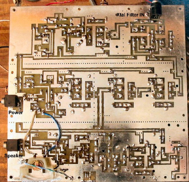
Making ConnectionsSee Making Loops for Connections on the Boards for making easy connections to the board for testing and completing the board. Three sets of loops are needed: Xtal Filter IN/Ground, 12 VOLTS/GROUND, and SPEAKER/Ground. Use long enough cable lengths so that the top board can be easily lifted to one side in case some diagnosis or corrections are needed on Board 1. ____Connect +12 Volts to the +12 Volt and Ground connections near the AGC Detector at the edge of the PCB. Picture____Be careful with polarity reversal. Use diode protection if a mistake might be made in connecting the board to 12 Volts. ____Use a 1-2 amp diode at the 12 volt main connection to prevent accidentally hooking up the receiver with reverse polarity. (This diode is not currently supplied with the kit.) The band end of the diode is connected to the 12 Volt connection and the anode end connected to the power supply. ____If you are using a 13.8 Volt power supply, put 3 diodes in series to drop the voltage to approximately 11.6 volts for the receiver. Cathodes (band side) go toward the receiver B+ and the anodes go toward the 13.8 Volt supply. The receiver likes 12 volts or a little below for best operation. Another type of connection is to use RCA phono connectors. I found that a lot of them can be soldered to the board. |
|
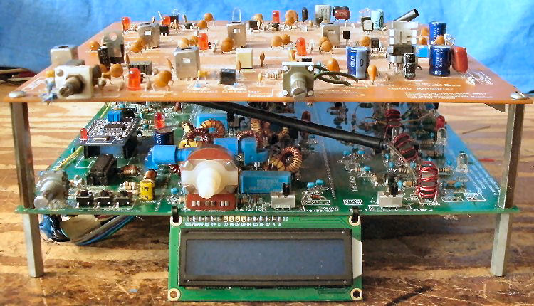
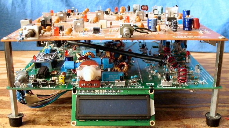
____Mount Board 2 over the female ends of the spacers coming up from Board 1. ____Use 6-32 screws to secure the board on the spacers. |
|
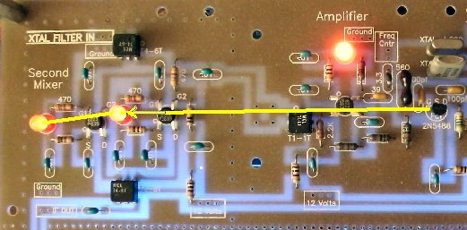
This is a good time to double check the soldering at the T4-6T transformers. Use a magnifying glass or take a picture with a camera at high resolution and take a second look to make sure they are good. TroubleshootingCrystal OscillatorWith the BLT, the same crystal, 3.547 MHz, is used in both filters. The 4.000 MHz crystal is the only one used and the crystal switching is locked onto turning on the 4.000 MHz crystal. The LEDs in the Second Mixer indicate drive from the Crystal Oscillator. Medium bright LEDs indicate that the oscillator and Mosfet Amplifier are working. |
TroubleshootingCrystal Oscillator MOSFET Amplifier____Crystal Oscillator Amplifier: The LED should be on.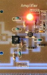 Troubleshooting455 IF Strip |
|
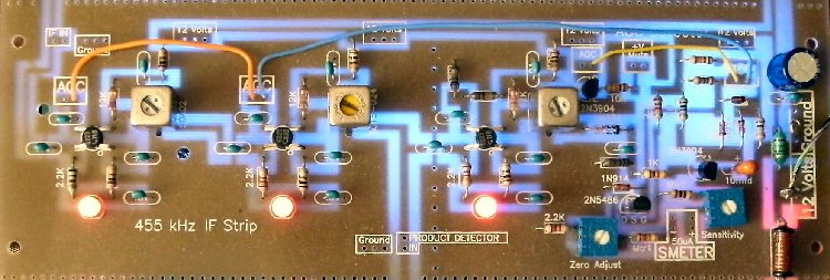
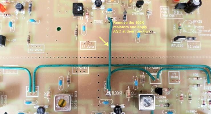
____455 KHz IF Strip: All three LEDs on the IF strip should be on. At one of the AGC connections, use a wire with clip leads and connect the AGC to Ground. The following modification will enhance AGC action if you are having problems with very strong AM Broadcast signals. Also works with the Ham Band version when dealing with local strong SSB or CW signals. If you are having a little distortion on strong signals, apply AGC to the Crystal Oscillator Amplifier as shown below. |
TroubleshootingBFO Amplifier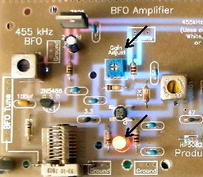 ____Turn the "Gain Adjust" counter clockwise so the LED is turned back on. TroubleshootingAudio Pre-Amp/Audio Amplifier |
|
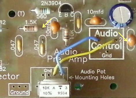
____Audio Pre-Amp/Audio Amplifier: Connect a speaker to the speaker terminals at the right of the 9779 audio amplifier, near the edge of the PCB. ____Touch a finger to the input of the Audio Pre-Amp, at the 1.5K resistor, next to the 10mfd capacitor. Hum from the 60 cycle house wiring should come out of the speaker. ____Touching the center connector of one of the 10mfd tantalums at the Bold "Audio Control" box will bypass the Audio Pre-Amp, and will also give a 60 cycle hum out of the speaker. If the 60 cycle hum test did not work at the 1.5K resistor, this test will isolate the problem circuit. Troubleshooting |
Send E-Mail || Amateur Radio Receivers || Back to SWL \ Ham Radio Instructions for the Blue Lightning Transceiver
