
|
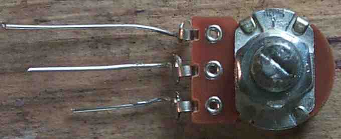
Solder bare hook up wire to each of the solder lugs. |
|
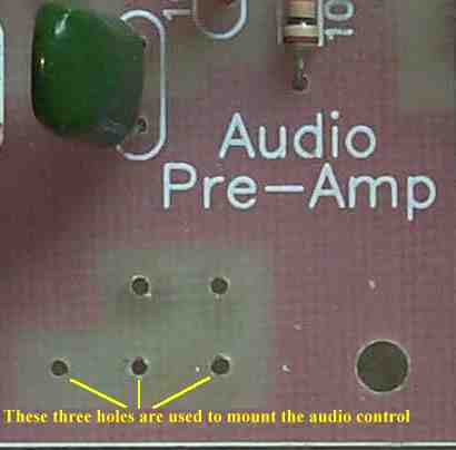
Note the three holes that the pot is inserted.
|
|
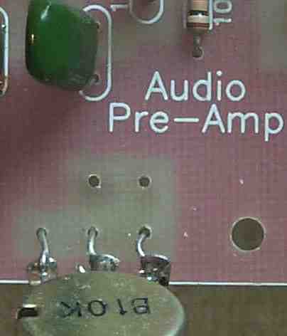
Picture shows the pot being installed into the holes.
|
|
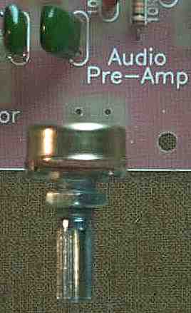
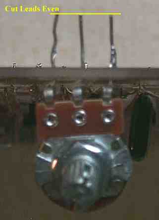
What the pot looks like fully installed.
|
|
Cut the wires even leaving about 1/2" to 3/4" leads.
|
|
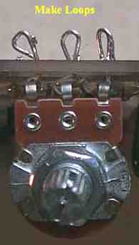
Bend each of the wires over with a needle nose pliers. Make the end of the wires touch the PCB board to help hold the pot onto the board. |
|
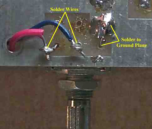
The loop on the right is bent backwards and soldered to the ground plane. A wire is soldered to the middle loop and inserted through the large hole to the left. A wire is soldered to the left loop and inserted through the large hole to the left. Using two different colored wires help identify the wires if they are run to the top of the board. The wires could also be soldered to the correct points below the board to have a cleaner appearance on the top side. |
|
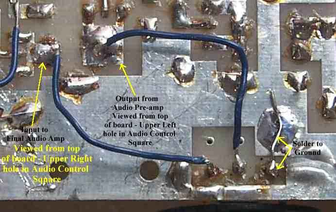
Shows connections for the Audio Control potentiometer if connected underneath the board. The wires can be run through the hole to the left of the pot and soldered on the top side of the PCB. The middle wire is connected to the upper left hole in the Audio Control Square (viewed from top of board). The left wire is connected to the upper right hole in the Audio Control Square (viewed from top of board). The right terminal of the pot is soldered to ground. Back to Installing the S-Meter |
Send E-Mail || Amateur Radio Receivers || Electroluminescent Receiver || Construction of the Kit