
|
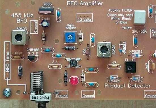
Note the blue PC mount "Gain Adjust" pot. Some kits will have a black PC mount pot for the gain adjust. Note the orientation of the 7805 regulator with the front of the part facing outwards from the BFO. |
|
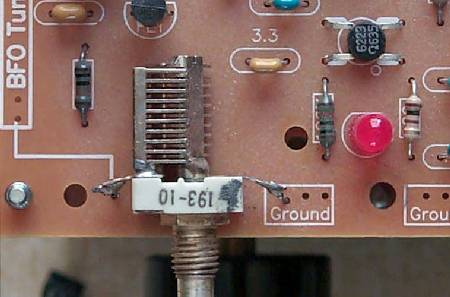
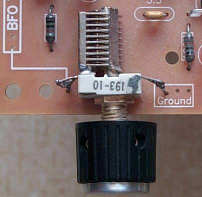
The BFO capacitor mounted on the board with the wires. Note that the lettering "193-10" is on top. This is important so that the shaft is grounded. If the shaft is not grounded, touching the knob for tuning would change the frequency of the BFO. Have the BFO capacitor half way opened when adjusting the BFO coil (Black core 455 kHz can). |
|
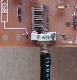
A front view of how the capacitor is mounted. Be sure to get the wires as tight as possible. |


|
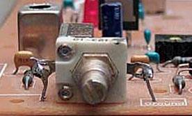
Shows the second piece over the first and then cut off. |
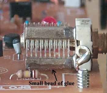 Arrow shows where to put the small line of glue. Don't overdo it here as it can get into the stator plates. |
Send E-Mail || Amateur Radio Receivers || Electroluminescent Receiver || Back to Ham Radio Instructions