

|
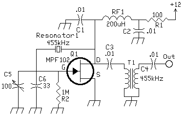
This circuit was used to stop all the BFO drift. The circuit is extremely stable. Turn the receiver off, and then on at any time and temperature, the BFO frequency is exactly the same. The resonator is a Murata CSB 455E. Murata's series number is CSBLA_E 430-509kHz. The data sheet is a .pdf file and the information on this resonator starts on page 28, "Ceramic Resonators(CERALOCK) Lead Type Two-Terminal CSBLA Series". The last time I checked I didn't find it on the site, but that doesn't mean you can't find it. T1 is a 455kHz IF transformer and may be eliminated if one is not available. This was a circuit I had lying around and had the transformer already wired in the output. It does help to eliminate harmonics from the oscillator. C5 is a panel mount variable capacitor. Value is not critical, just test the range to make sure you can reach both sides of zero beat. C6 can be adjusted for different values of C5. RF1 is an RF Choke that can be any value from 200uH to 1mH. The FET can be any part number. Some common ones other than the MPF102 are the 2N5486 or 2N4416. The application above covers 452.6 to 455.0 kHz. This is the perfect range for the receiver. The circuit above could be improved to expand the range, but an extended range was not necessary. The amount of drive delivered to the product detector should be on the low side. Driving the product detector too hard will cause leakage to the IF strip and cause oscillations. If you are listening to a CW signal that suddenly jumps around, oscillations in the IF strip from too much BFO drive should be investigated. No problems were experienced with the Resonator/amplifier shown above, but the Hartley (below) with a MOSFET amplifier had to be tamed down. This circuit was inspired by the article "Ceramic Resonators for Cheap and Cheerful VFOs", by Jack Ponton, GM0RWU. Also check out "Mixer VFOs for the HF bands." This article was quite an eye-opener that showed a huge range could be covered by resonators. He shows a circuit that covered 13.990 to 14.280 MHz. The article is well worth reading. |

|
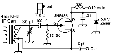
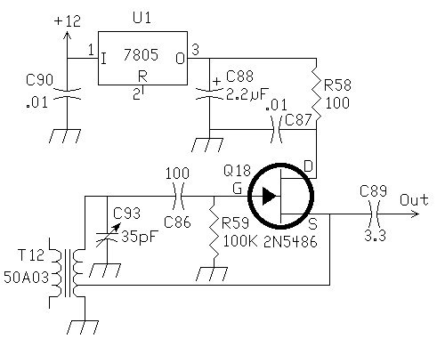
This is a Hartley oscillator circuit, using a 455kHz IF can. The 35pf variable capacitor is a panel mount type and is mounted on the front panel. I used 50 ohm miniature coax cable to wire the capacitor to the front panel. You need a 455kHz IF can that has a center tap on the coil. Almost all of them have the tap. You can raise the injection level by changing the 10 pf output capacitor to a higher capacitance. You can also use the variable gain MOSFET amplifier and vary the injection level from the front panel. For better isolation from the 12 Volts line, use a 7805 5 volt regulator. Remove the zener diode and replace the 330 ohm resistor with a 100 ohm resistor, and feed the output of the regulator to the 100 ohm resistor. A 2.2mfd electrolytic capacitor needs to be placed at the output lead of the 5 volt regulator. Below is the circuit using a 7805 regulator.  References"Ceramic Resonators for Cheap and Cheerful VFOs", by Jack Ponton, GM0RWU. Also check out "Mixer VFOs for the HF bands." "Voltage Controlled Oscillator Uses Ceramic Resonators", By Albert D. Herlfick, K2BLA, Ham Radio, June 1985, pp 18-26. "A High-Stability BFO for Receiver Applications", subtitled "Two VCXOs Work Together to Provide High Performance", By Peter J. Bertini, K1ZJH, Ham Radio, June 1985, pp 28-31. Ceramic Filter and Resonators This page investigates ceramic filters and resonators and explains what a ceramic filter is and how you can use it. |
 Send E-Mail|| Amateur Radio Receivers || Super Receiver || Super Receiver Circuit Details
