|
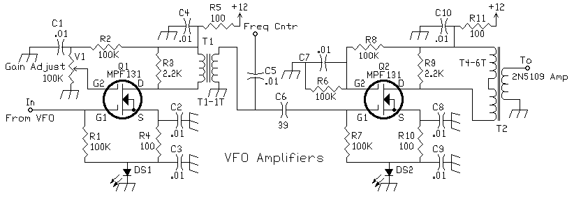
The 100K variable resistor (Gain Adjust) can be mounted on the front panel. It is also useful to mount the LED from this amplifier on the front panel to remind you of how much injection you're using. Mount this circuit (with the VFO) close to the front panel in order to keep leads short.
I would fire up the receiver and have no signals, until I realized the VFO amplifier LED was very dim. The brightness of the LED indicates injection level. Very bright - highest injection, low brightness - lower injection levels.
Higher injection levels give greater conversion gain which equals better sensitivity. Lowering the injection level kept strong signals from modulating the noise level, an aid when trying to copy a weak signal right next to a very strong signal. I found
it helpful during contesting and working DX.
The Frequency output capacitor can be changed to vary the drive level to the counter. As little as 18pf can be used to help isolate the frequency counter birdies from getting into the VFO amplifier chain.
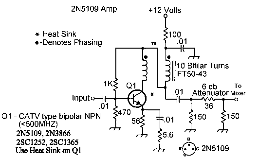
2N5109 Amplifier

The 50 ohm resistive pad can be changed, or even left out, to set the proper injection level to the diode mixer.
This circuit is the post-mixer amplifier in the Progressive Communications Receiver.
|


 Send E-Mail || Amateur Radio Receivers || Super Receiver || Super Receiver Circuit Details
