
|
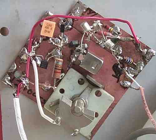
The BFO tuning cap is used to hold the circuit in place against the front panel of the receiver. It should be shielded, but since the cabinet of the HQ140X is so large, and all the other circuits in the immediate area were shielded, no problems occured. The CFU455F resonator is the yellow rectangle at the top of left of the PCB, and the 2N5486 oscillator is directly below the resonator. The two transistor amplifier/buffer is on the top right. Too much output from this circuit has caused oscillations in the IF strip. I found it better to lower the output from the BFO and compensate by using more audio gain. This circuit has worked perfectly without any problems. For other circuit designs, check out "Ceramic Resonators for Cheap and Cheerful VFOs", by Jack Ponton, GM0RWU. Also check out "Mixer VFOs for the HF bands". |
 Return to: Amateur Radio Receivers ||
Super Receiver || Super Receiver Circuit Details || BFO Circuit
Return to: Amateur Radio Receivers ||
Super Receiver || Super Receiver Circuit Details || BFO Circuit