

|
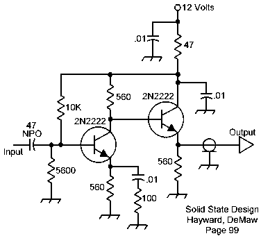
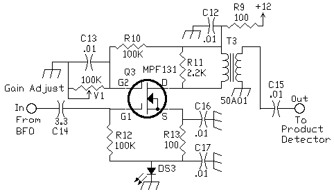
The circuit above is used as the buffer/amplifier for the resonator circuit. The one below was used for the Hartley BFO. The above circuit is the VFO Transistor Buffer circuit listed in the VFO page. A .01 is used at the input instead of the 47pf shown, and a 100pf is used to couple the output to the product detector. The output of this BFO/amplifier is considerably less than the one below, so the variable gain option was unnecessary.
|

|
T3 is a 455kHz IF transformer. V1 can be either a PC mount or panel mount 100K potentiometer. The 100K pot adjusts the output to the product detector. V1 is adjusted to set the audio volume to the preferences of the operator. Once set it is usually left alone. However, when a panel mount V1 is installed, it can be used for fine tuning the reception of very weak signals. Setting V1 where the LED just barely lights gives the lowest noise output in the audio.
|

Send E-Mail || Amateur Radio Receivers || Super Receiver || Super Receiver Circuit Details
