
Bottom PlateThe following text describes how to put the receiver together as shown on the Home Page. If you have a problem when testing the boards, go to "LED Diagnosis/Troubleshooting" for help. ____Use a piece of PCB, aluminum plate, or steel plate to use as the bottom piece of the receiver. Dimensions are 8 1/2" by 8 1/2", the same size as the boards. (A drilled PCB plate will be included with the kit as supplies last.) |
|
Instructions if drilled bottom plate is not included with the kit. ____Using Board 2, since it has not been built, as a template, drill holes through the bottom plate at the four corners. (Holes have already been drilled in the PCB material with most kits.)With the 6-32 size hardware supplied with the kit the holes need to be enlarged with a 9/64" drill bit. The holes are originally drilled for 4-40 size hardware. Note: If the board does not use the Vackar VFO (DDS VFO only), you do not need to drill the following holes. ____Drill two holes in the VFO area. Two holes are located above and below the text "VFO". One is above the text "120 Poly" a little ways to the right of the 3.3 pf capacitor and immediately below the text "Gnd". The other one is at the front of the VFO immediately below the text "Mount Photo High" at the front edge of the board. |
Mounting Board 1____A space of 2 1/2" is needed between the bottom plate and Board 1. This leaves enough room for the Main tuning capacitor, the LED Frequency Counter, DDS VFO (mounted at slight angles), Frequency Stabilizer (if used), and Transmitter components. If the spacers come pre-assembled, the longer ones are used between the bottom plate and Board 1. If not, screw together two of the shorter spacers together. They have one male end and one female end. ____Connectors for +12 Volts, Speaker and Antenna. These connectors are not supplied with the kit. The prototypes used RCA connectors that were soldered to the board. If a Transmitter is added to the bottom board, these connectors are added at the time the transmitter is constructed.____Spacers (that use 6-32 hardware) are supplied with the kit. Two male/female spacers 1 1/4" long are attached and mounted with the female end on the bottom plate and attached with 6-32 screws. The holes at these locations have been drilled with a 9/64" drill bit to accommodate the 6-32 hardward. All other mounting holes are 1/8" that accommodate 4-40 hardware. ____The minimum mounting holes is 6, one on each corner, one at the VFO next to the text "3.3" (used only if Vackar VFO is built), "7 Turns" (used for DDS VFO only build) and the "Mount Photo High" at the front of the board (used for both builds). If you use additional mounting holes and you use 6-32 hardware, but sure to enlarge the holes with a 9/64" drill bit. The following pictures show a DDS VFO only build showing one way to mount the DDS VFO. The display will be mounted onto the bottom plate with small right angle brackets and screws/nuts. The best for lowest noise from a DDS VFO, mount it in a seperate box, easily made with PCB material, to completely shield it from the receiver. With the DDS VFO mounted in the receiver, as shown below, tuning noise will be heard outside of the peaks of the bands. Band noise, up to 15 meters, will hide the tuning noise. On 12 and 10 meters, tuning noise and spurs will be heard clearly, but signals can be heard clearly, if not directly on top of a spur. |
|
Note: There is one place on the front of Board 1 where a spacer can short 12 Volts to ground. |
|
The "Be Careful" arrow points to the spacer and the rectangle pad above the spacer (with another arrow) that are shorted when a spacer is placed in this hole. Some of the pad can be removed to undo the short. Vackar VFO Build Spacer InformationNote: There must be a very good connection between the spacers and the ground plane around the VFO. If the spacers do not have a good ground connection the VFO frequency will be very unstable. The frequency will do quick jumps, especially when the main tuning capacitor is adjusted.  Arrows show location of holes. Picture
____Clean the ground plane areas around the holes surrounding the VFO. There are three holes: one at the corner, the next hole to the right underneath the Photodiode, and one next to the "Frequency Cntr" box at the output of the VFO. Best to use fine grit (220 to 320) sandpaper or even lightly tin the areas with solder.
If there is any problem with VFO stability, the first thing to check are loose spacers around the VFO or bad ground connections to the spacers. When the spacers become loose, the VFO frequency will be very unstable. Loose spacers around the VFO will cause incredible instability. When the spacers are retightened, the VFO will run OK. A maximum of 12 places can be used to mount Board 1. The other holes around the VFO would be the first place to add mounting holes, especially the one to the right of the VFO coil next to the "Gnd" connection. Please Note: The mounting holes are 1/8" to accommodate 4-40 hardware. Some have been drilled to 9/64" to accommodate 6-32 hardware. Depending on the size that will be used, note the different size holes. |
|
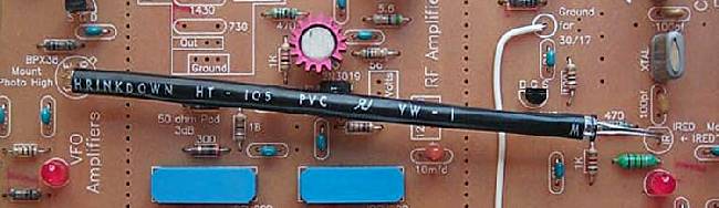
____Connect +12 Volts to the +12 Volt and Ground connections near the output of the VFO. ____Be careful with polarity reversal. The 10mfd tantalums may explode and some traces may be burned going to the 7805 and First Mixer. Use diode protection if a mistake might be made in connecting the board to 12 Volts. ____Use a 1 amp diode, 1N4001 or similar at the 12 volt main connection (band goes to 12 Volt connection) to prevent accidentally hooking up the receiver with reverse polarity. (This diode is not currently supplied with the kit.) The band of the diode is connected to the 12 Volt connection. Other end is connected to the power supply. Bandpass Filter____Turn Bandpass Switch to 40/30/20 side. A mistake was made in the text, it reads 40/30/17.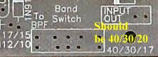 ____ If the Vackar VFO was Built: Bandpass Filters Section: Measure, cut, (See Preparing the Heat Shrink Tubing) and install a short piece of 3/16" black heat shrink tubing (Bag 6) between the IRED at the bottom of the 17/15/12/10 Bandpass Filter and the Photodiode next to the 10.455 yellow trim capacitor right to the immediate left of the IRED. 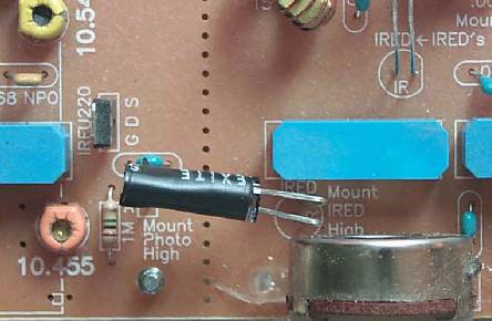 Picture (Picture from ELR is used.) If the 40/30/20 LED at the Bandpass Filters is bright/dim, shield any light (overhead shop light, etc.) that is hitting the Photodiodes. The 40/30/20 LED should go out. TroubleshootingBandpass Tuning Pot____Place a VOM in DC Volts position, and measure the voltage at the FILTER TUNE Bold circle, and check its range while running the Filter Tune pot from end to end: +.12 to +11.7 Volts (within a volt).TroubleshootingFirst Mixer/Post-Mixer Amplifier____First Mixer: Both LEDs should be on and just slightly lower in intensity than the Post-Mixer Amplifier LEDs. Adjust the "Gain Adjust" pot at the first VFO Amplifier counter clockwise, and the mixer LEDs should turn off.____Readjust the "Gain Adjust" pot clockwise so that the Mixer LEDs are full on. ____VFO Post-Mixer Amplifiers: The LEDs of the two Post-Mixer Amplifiers should be on. TroubleshootingCrystal Filters____Crystal Filters: Measure (4 1/2" length), cut, (See Preparing the Heat Shrink Tubing) and install the piece of 3/16" black tubing (Bag 6) between the 40/20 IRED and the Phototransistor at the VFO Amplifiers. |
|
Other types of black tubing such as vacuum hose, black straws, or black plastic tubing may also be used. Black is the preferred color, other colors are not as effective. ____The LED below the 3.547 MHz crystals should be on. Move the Crystal Filter switch to the 4.000 side, the LED below the 4.000 MHz crystals should turn on, and the LEDs at the VFO should turn off. With the Bandpass Filter switch on 17/15/12/10, the Crystal Filter switch on 4.000, and the Bandpass Tune pot tuned to 17 meters, the receiver will be on 17 meters. With the Bandpass Filter switch on 40/30/20, the Crystal Filter swtich on 3.547, the Bandpass filter can tune for either 40 meters. If the LEDs stay on at the VFO, light (overhead shop light, etc.) is hitting the Phototransistor. The Phototransistor is sensitive to visible light, as well as Infra-red. Also, the back side of the Phototransistor is clear and bright light directly on the back side of the device will turn it on. Watch for this problem when operating the receiver outside in sunlight (i.e. at an outdoor hamfest). Troubleshooting |
Setting the Vackar VFO FrequenciesIf you have purchased the LED Frequency Counter, this would be a good time to build the Frequency Counter kit. Go to Frequency Counter Construction page for instructions. If you have already built the kit, short the "Osc In" to "Gnd" on the board so it will work as a regular counter. Use the "VFO In" and "Gnd" to make the measurements. If you are using the AADE DFD2 Frequency Counter use these instructions for Setting the Frequencies. The following procedure will set up the receiver for the first 100 KHz CW portion of the 40 and 20 meter bands of the receiver. The 14 MHz VFO, with a 180 KHz range, will cover all the 30 and 17 meter bands. See "40 and 20 Meter SSB Setup" if you want to tune the SSB portion of the 40 and 20 meter bands. ____Connect a Frequency Counter to the output of the VFO labeled VFO OUT. There should be plenty of drive for any frequency counter. Note: See "VFO Troublshooting" if you don't have enough drive for the Frequency Counter. ____Set the switches to 30 meters. Picture____Set the 2/8 ceramic trim pot (labeled 14.068) to its middle position. Line up the slot in the adjustment screw with the capacitor pins, with the rotor plate on the end with the arrow. The rotor plate is the part of the top with the metallic color. ____Spread or compress the VFO toroid winding to set the frequency as close to 14.068 MHz as possible (or 14.066 MHz - Gives some room at the low end of the band.) ____Secure the VFO toroid by whatever means you have decided. One option is a 4-40 screw/nut and 3/16" rubber grommet. If neither are available, just wax it on the board, see next instruction. Picture ____Pour melted wax from a common household candle onto the toroid and ferrite core for maximum frequency stability. Picture ____After the wax has cooled, recheck the 14.068 MHz freqeuncy. ____Reset the 2/8 ceramic trim pot labeled 14.068 to 14.068 MHz or 14.066 MHZ. Note: All tuning to make the frequency reach 14.068 is done by modifying the turns on the toroid. If the frequency will not reach 14.068, but reaches only 13.3 to 13.5 MHz with the turns moderately spread apart, remove one turn on the toroid. If the frequency is too high, add a turn to the toroid. (This may require rewinding the toroid for a clean appearance, but having the frequency read too high, >15MHz, is unlikely.) ____Set the switches to 40 meters. Picture The LED next to the 10.545 relay inside the VFO should be on. ____Set the switches to 20 meters. Picture Both LEDs on the VFO should be on. If you have already built Board 2, then go to Mounting/Testing Board 2. |
Send E-Mail || Amateur Radio Receivers || Back to Back to Instructions for the SuperLuminescent Receiver
