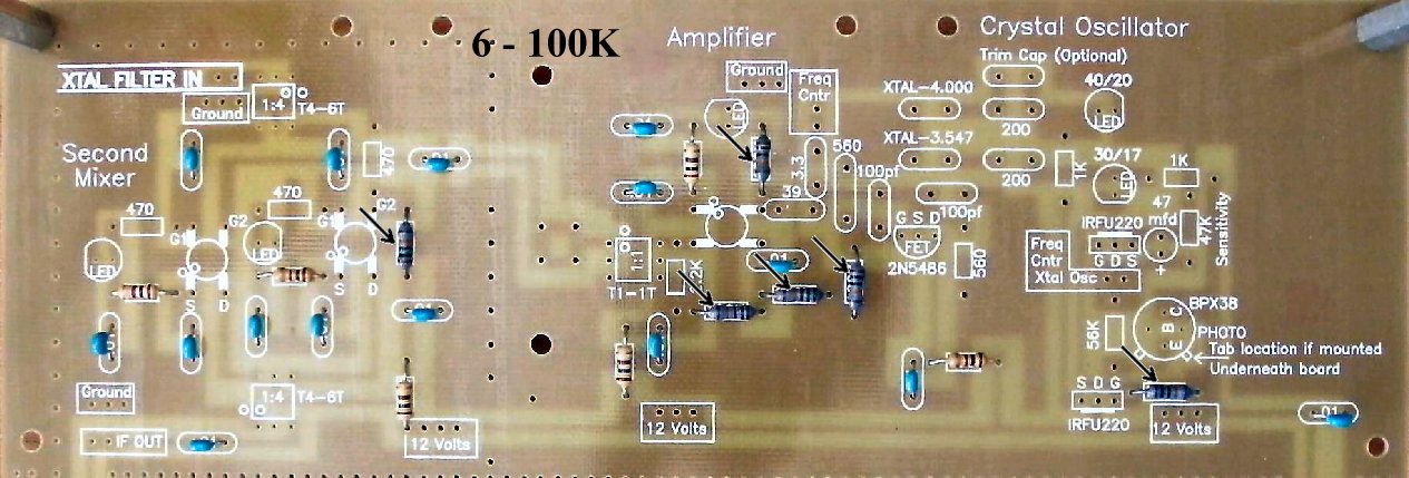
To learn about the Second Mixer, read the
Circuit Details - Second Mixer
before building this section.
To learn about the Crystal Oscillator, read the
Circuit Details - Crystal Oscillator/Amplifier
before building this section.
|
____Mount spacers on each side of the board on the four corners to provide support for insertion of parts and easy soldering. Picture |
|
Insert all the components that have their values inside the footprint. They are the following: ____15 - .01 capacitors (Bag 3) |

|
Solder |
|
Solder |
|
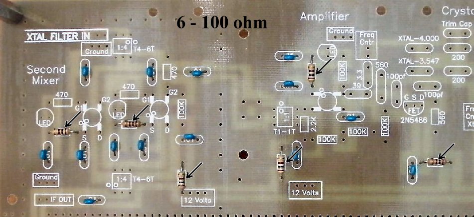
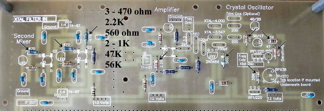
Solder Resistors:____2 - 1K (Bag 3), One is located on the left side of the 30/17 LED, and one is located on the right side of the 30/17 LED |
|
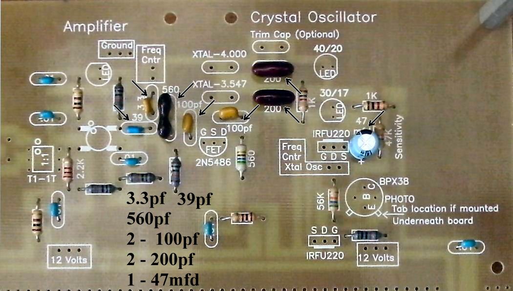
Solder Capacitors (Going left to right on the board):____2 - 100pf NPO (Bag 3), Located at the left side and above the FET (2N5486). Orange color, short leads flared out, labeled "101". |
|
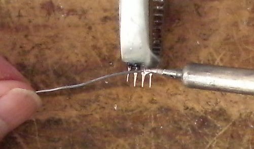
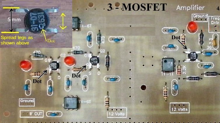
Solder Crystal Oscillator Switching, Crystals, and PhototransistorSLR ModificationsIn the SLR, when using a DDS VFO only, all the crystals in the Crystal Filter will be the same. The 3.547 MHz crystals will be in the parts for both Crystal Filters. By changing the caps used in the Filters, a narrow filter (300pf caps) and a wide filter (39pf caps) can be built and switched by the Crystal Filter switch. Using 3.547 MHz Crystal Filters: Using 4.000 MHz Crystal Filters: If you decide to install the Phototransistor, so it won't get lost, you can install it above the board (easier) or below. 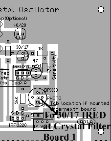 ____1 - BPX-38 Phototransistor (Bag 5), transistor looking part with three leads and a glass face, the "B" pin is not connected to any traces and can be soldered after the device has been aimed at the IR LED, if desired (not necessary). 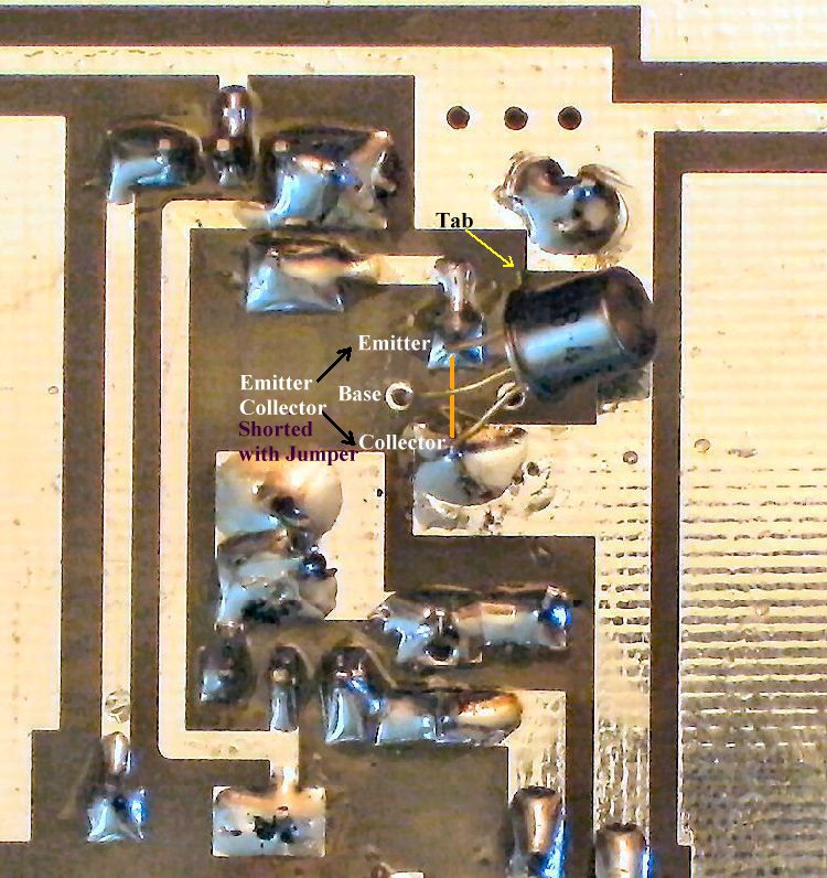 Solder Crystals/MOSFETs____1 - 4.000MHz crystal (Bag 4), The markings are "4000 KSS 2FT". 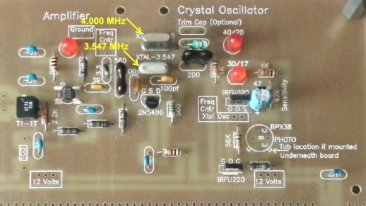 Solder ____3 - MOSFETS (Bag 2), (Picture) static sensitive part, touch a ground wire before taking it out of the bag, notice the dot on MOSFET (may be difficult to see, hold at an angle to a light source and you can see the shadow of the dot), the dot is located to the left of the second line of the text on the MOSFET. A dot is placed outside the footprint so that you can double check your placement after it has been soldered to the PCB. The leads on each side of the part need to spread apart slightly to fit the footprint. |
|
Solder |
|
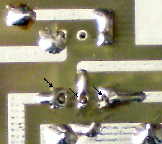
____Check the dot on the MOSFETs and the Minicircuits transformers. |
|
|
Send E-Mail || Amateur Radio Receivers || Back to Instructions for the SuperLuminescent Receiver