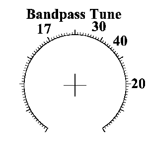

SwitchesIf you would like to use a rotary switch for bandswitching, see How to wire a Rotary Switch. Pictures of the SPDT bandswitches for all the bands - 40, 30, 20, and 17. The switch that controls the Crystal Filters determines which bands the receiver will hear. The text on either side of this switch indicates which bands are activated, either 40/20 or 30/17. This switch, using the IR LEDs at the crystal filters, turns on the appropriate VFO frequency and crystal oscillator frequency. The switch that controls the Bandpass Filters turns on the filter that will pass the band activated by the Crystal Filters. The text on each side of the switch is 20/17 on the left and 40/30 on the right. To make it simple, just turn both switches to the band you want to hear. For example, to hear 40 meters, the switch at the Crystal Filter is switched to the side that says 40/20. The Bandpass switch is switched to the side that says 40/30. Then turn the Filter Tune pot until you hear band noise or signals. To hear 30 meters, switch the Crystal Filter switch to 30/17 and the Bandpass switch to 40/30. Read below for the position of the Filter Tune pot for the four different bands. Bandpass Filter Tune Potentiometer
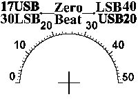
The image above is a .gif file that can be right clicked and downloaded. Open it in a picture program, resize and print to help find the bands. The 30 and 17 meter bands have two peaks, one at the indicated marks and one slightly off to one side. Either works fine. The 40 and 20 meter band peaks will be very strong. Align the knob being used with one of those bands and it will be very close to the others. If the 40 meter band is wide open, there will be another peak right below the peak for the 40 meter band. Tune slightly above this other peak and the 40 meter band will be found. Labels for all the controls, except for the main tuning capacitor, can be found at "Labels for the Receiver". They are large so they can be sized to whatever is desired. Right click the images, download, resize in an image program, and print. BFO Adjustments Image shows which way the sidebands line up. For 40 and 20 meter SSB, the BFO cap is adjusted to the right of zero beat. For 17 meter SSB, the BFO cap is adjusted to the left of zero beat. The standard sideband settings for the bands are noted on the image. LSB (Lower Sideband) for 40 and 30 meters. USB (Upper Sideband) for 20 and 17 meters. Note: For the image settings to be correct, start with the BFO fully meshed (closed) and turn the BFO knob clockwise. Picture For a large copy of the receiver labels that you can resize to fit with a picture program, go to "Labels for the Receiver".Main Tuning Control at the VFOWith the capacitors used as given in the instructions, the bandwidth of all the bands is about 100 to 150 KHz. This was found to be a comfortable tuning range for the tuning capacitor with the large knob included in the kit. For wider bandwidths consider using a reduction drive for easy tuning. A CD ROM attached to the shaft, turned by a modified pot, will work and construction information is provided. See VFO Tuning with a CD ROM. Audio ControlThis potentiometer can be either 5K or 10K. As the pot is turned clockwise, volume should increase. If it decreases, switch the leads to the outer ends of the soldering tabs. A plastic/insulated knob should be used, as hum and commercial stations can be picked up through your hand into the pot to the audio amplifier. If the pot has a metal case, a ground wire soldered to the case of the pot will reduce pickup problems. Ground connections were placed in the area for this reason. |
Send E-Mail || Amateur Radio Receivers || Electroluminescent Receiver || Back to Construction of the Kit || Back to Ham Radio Instructions for the Kit
