
To learn about the First Mixer, read the
Circuit Details - First Mixer & Amplifier
before building this section.
To learn about the Crystal Filter, read the
Circuit Details - Crystal Filter
before building this section.
To get the best print of the above picture, right click the mouse on the image, select "View Image". In the new browser window, click print, set layout to "Landscape", then "OK" to print.
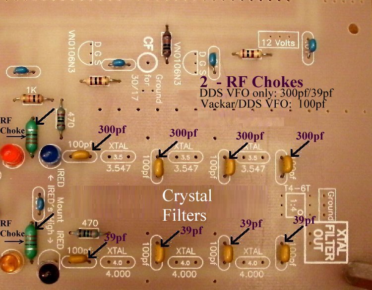
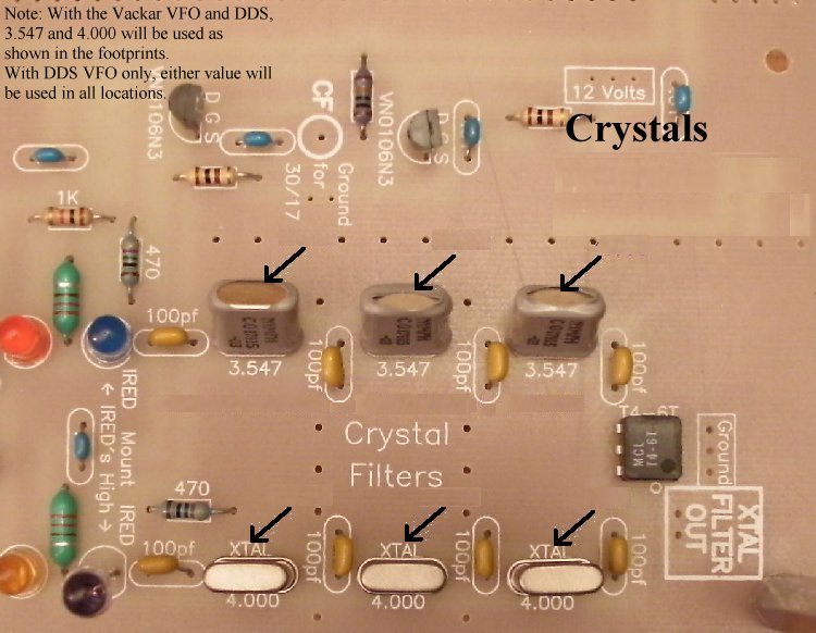
PreparationInstructions on winding the cores are below, too. If you need more help in understanding how to wind the bifilar cores, come back here and click on this link. This section uses the remaining FT50-75 ferrite cores (Black colored, Bag 4). Click on the link above for pictures and text on winding the coils for the mixer. The FT50-75 cores are not as wide as the FT50A-75 cores as shown in the winding instructions (in case you notice). The center transformer of the mixer is only a ten turn bifilar coil. The coils at each end of the mixer are ten turn bifilars with a 5 turn secondary. Crystal Filter BandwidthAll the capacitors in the filters are labeled 100pf. Four are used in each filter, one at the front of each filter, two in the middle, and one at the end. If the Vackar VFO and a DDS VFO are used, the crystal filter will use both the 3.547 MHz and 4.000 MHz freqency crystals as shown on the board. When the DDS VFO is used, the crystal filter the PIC uses is switched on. If only a DDS VFO is used, the same frequency crystals will be used in both filters. The PIC will be programmed for the crystals used. 0ne is built for a narrow bandwidth and one for a wide bandwidth. Therefore, the 100pf capacitors are replaced with the capacitors as noted below. One filter uses 300pf caps for achieving a narrow bandwidth for CW reception. These caps/crystals can be placed in the filter where 3.547 crystals were placed. The other filter (labeled with 4.000 crystals) uses 39pf caps for achieving a wide bandwidth for SSB reception or for causal listening in the bands. When using the crystal filter switch at the front of the board, your narrow filter will be the side labeled 3.547 and the wide filter will be labeled 4.000. You can select any bandwidth you like by using capacitors between the values noted above. The same capacitor value needs to be used throughout the filter. Filter simulator programs can be used to further tune the filters for better performance. In this case, the capacitor values will be determined by the simulation program. Note that capacitors could be placed above (through the holes) and below the board (soldered to the pads) for convenience. Board 1 Replacement Only |
|
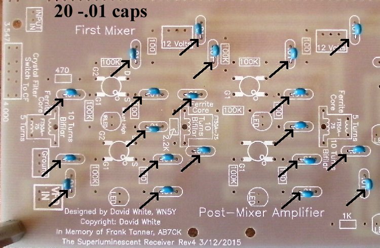
____20 - .01 capacitors (Bag 3) |
|
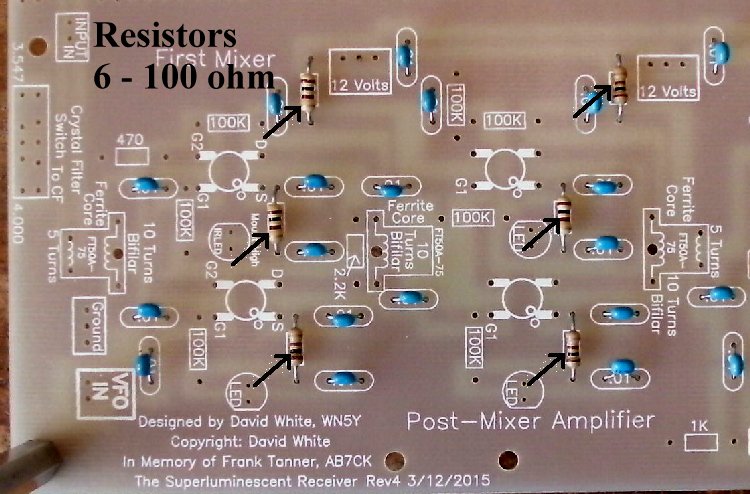
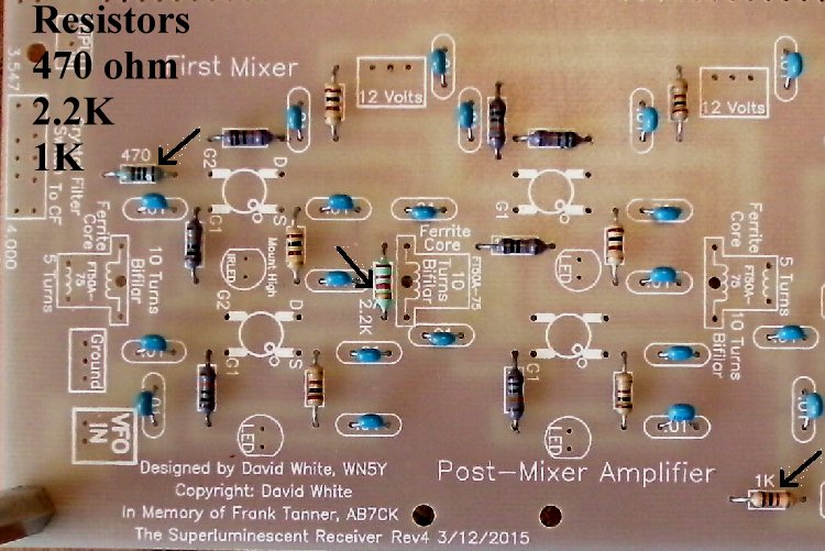
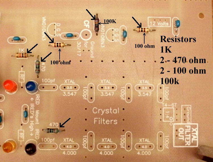
____6 - 100 ohm resistors (brown, black, brown) (Bag 3) |
|
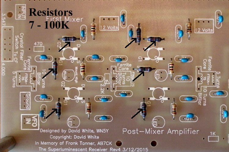
____7 - 100K resistors (brown, black, yellow) (Bag 3) |
|
____1 - 1K (Bag 3), Located at the top and bottom of the input to the crystal filters. |
|
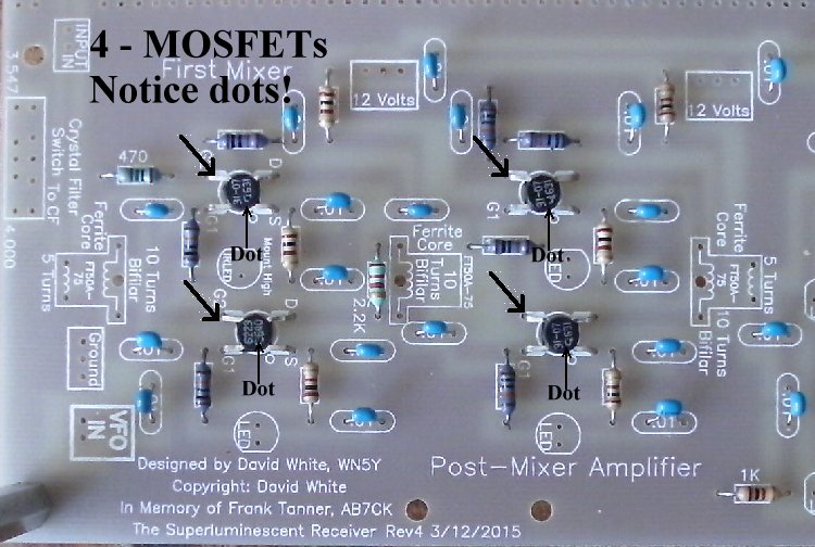
____4 - MOSFETs (Bag 2), (Picture) static sensitive part, touch a ground wire before taking it out of the bag, notice the dot on MOSFET (may be difficult to see, hold at an angle to a light source and you can see the shadow of the dot), the dot is located to the left of the second line of the text on the MOSFET. A dot is placed outside the footprint so that you can double check your placement after it has been soldered to the PCB. The leads on each side of the part need to spread apart slightly to fit the footprint. |
|
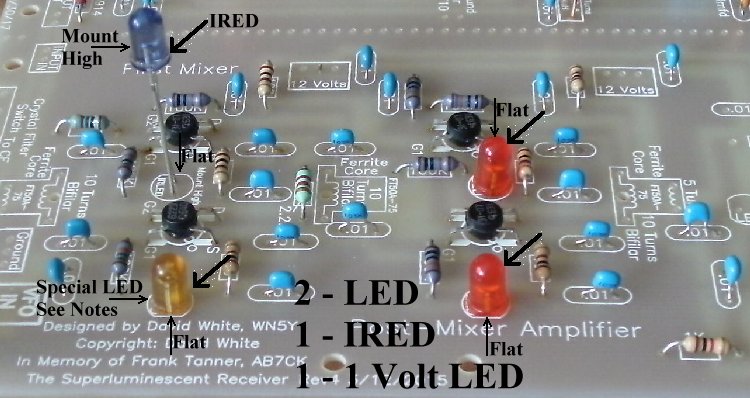
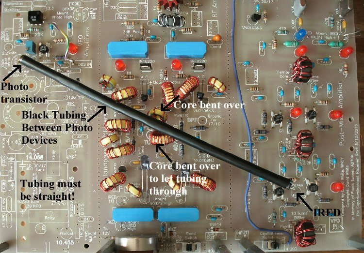
____3 - LEDs (Bag 3), Red colored, match the flat on the LED to the flat on the footprint. The short lead is on the same side as the flat. Note: If you ordered the Bright Red LEDs, they can replace the ones in the mixer. See Modifying the LEDs. ____1 - IRED (Bag 4), Smoky colored, on a cardboard strip, do not cut the leads off the strip, tear the IREDs off the strip and clean the bottom of the leads. The short lead is on the same side as the flat. Mount as high as possible and match the flat on the IRED to the flat on the footprint. Bend the IRED toward the Phototransistor at the MOSFET VFO amplifier. Aim the phototransistor back toward the IRED. A piece of black tubing will be placed between the two devices to direct the IR light. |
|
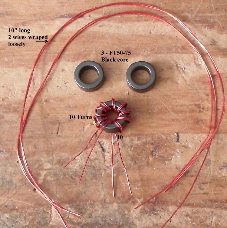
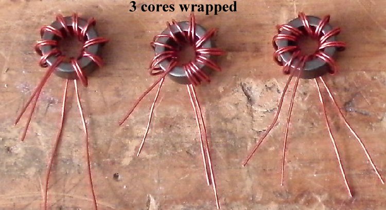
____3 - FT50-75 ferrites (Bag 4) and enameled wire (Bag 6) |
|
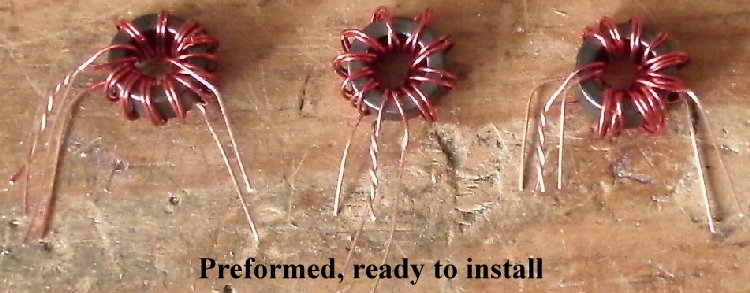
Scrape the lead wires of their enamel coating. Use a VOM and arrange the wires as shown in the picture below putting the ones having continuity (zero ohms) on the same side. Wrap one wire from the top to the opposite side bottom wire. |
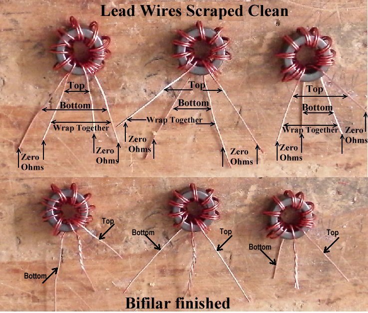
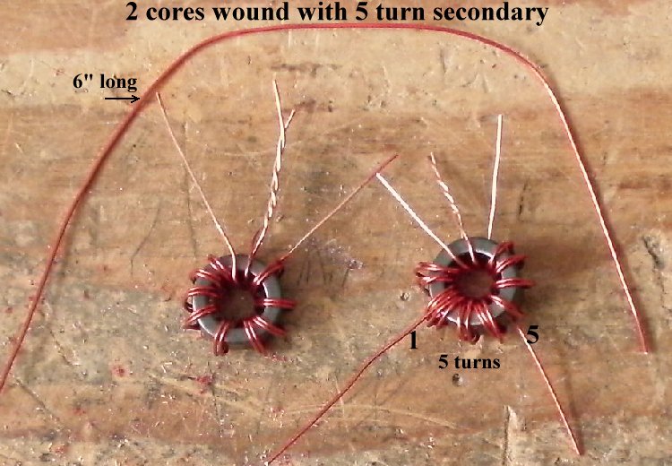
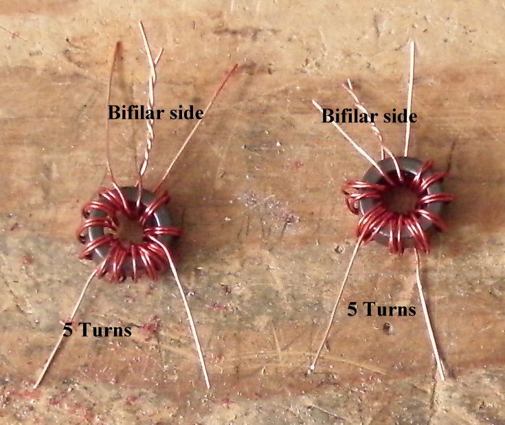
Two of the Bifilar windings need a 5 turn Secondary |
Bend the leads as shown below for easy insertion into the PCB |
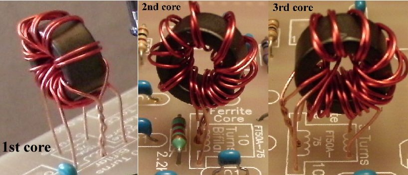
Please Check!Carefully inspect the wires on the bifilar side of the cores and make sure they are not shorted. There is no ohm meter check for this error, so you must look carefully. Make sure the bare parts of the wires are not touching! Double check underneath the board to make sure there is not a solder bridge between the leads. The second and third core (counting from the front) carry 12 Volts. If the bifilar leads are shorted there will be some burning (smoke) of the wires, the LEDs will not light up, and the 100 ohm resistor that feeds 12 Volts to that core will need to be replaced if it is black or shows open with a VOM. You can check the voltage at the 'D' pin of the 2 MOSFETs (both the SB Mixer and SB Amplifier) for 11 to 12 volts. If one 'D' pin shows 6 volts and the other about 11 Volts, then one lead of the bifilar core is unsoldered. If neither has about 11 volts, check the center lead of the bifilar core. |
|
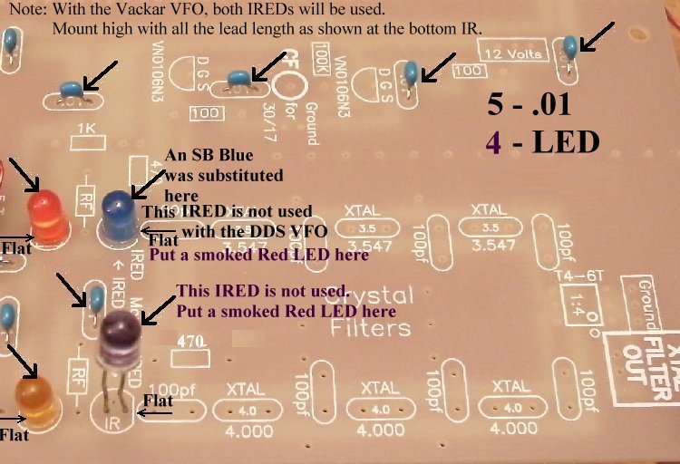
____5 - .01 capacitors (Bag 3) For using a DDS VFO only, follow the following instructions:____4 - LEDs (Bag 3), Red colored, match the flat on the LED to the flat on the footprint. The short lead is on the same side as the flat. Note: If you ordered the Super Bright LEDs, you can place two of them at the input of the crystal filter, next to the IR LEDs. Use different colors to help crystal filter identification. If you ordered the Bright Red LEDs, they can replace the ones in the mixer. See Modifying the LEDs.The IRED, in the middle of the board, is not used. A regular smoked Red LED is placed here. In the picture an SB Blue LED was put in its place for testing. The IRED near the outside of the board is not used. Both filters are 4.000MHz and the Crystal Oscillator does not need to be switched. A smoked Red LED is used here. For using the Vackar VFO and a DDS VFO, follow the following instructions:____2 - LEDs (Bag 3), Red colored, match the flat on the LED to the flat on the footprint. The short lead is on the same side as the flat. Note: If you ordered the Super Bright LEDs, you can place two of them at the input of the crystal filter, next to the IR LEDs. Use different colors to help crystal filter identification. See Modifying the LEDs.____2 - IREDs (Bag 4), Smoky colored, on a cardboard strip, do not cut the leads off the strip, tear the IR LEDs off the strip and clean the bottom of the leads. Located at the input to the crystal filters, right next to 100pf caps. You will be using the IREDs with the Vackar VFO, so put them in the IRED footprints. |
|
____2 - 100 ohm resistors (brown, black, brown) (Bag 3) |
|
____2 - RF Chokes (Bag 3), Footprint on PCB is rectangle with square edges, "RF" inside the rectangle. Choke is about the size of a 1 watt resistor with rounded edges. For DDS VFO only with same crystal in all places: For Vackar VFO and DDS VFO, both crystals will be used as shown in the footprints. |
|
____2 - VN0106N3 (Bag 2), static sensitive part, touch a ground lead before removing the part from the bag. Match the flat on the part to the flat on the footprint. Spread the outside leads slightly to fit the footprint. Marked "SI N, 0106, 8302". |
|
For DDS VFO only: For Vackar VFO and DDS VFO: |
|
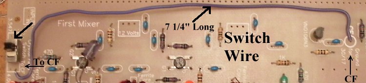
____1 - SPDT Miniature PC Mount switch (Bag 5), There is a switch footprint in front of the First Mixer. There are two hole patterns. Mount the switch in the holes that work. Picture If you click on 'Picture', click 'Back' on your browser to return here. |
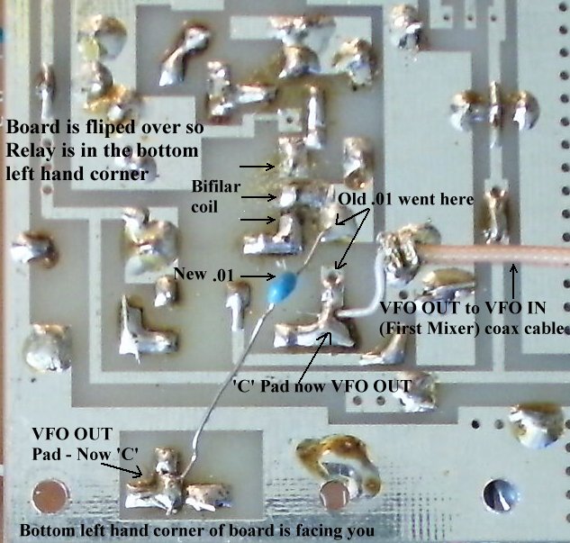
Soldering the coax between the 'VFO OUT at the end of the VFO board to the 'VFO IN' at the front of the First Mixer |

|
Go to Relay Error Fix to see the fix. An error was made at the relay connections. Solder the shield of the coax cable to the ground plane next to its new location right next to the hole of the old .01 cap. (Labeled 'C' on top of the board) Next, solder the center conductor of the coax on that pad which has the hole for the old .01 cap. |
|
The picture below shows the connection to the "VFO IN" at the Mixer. 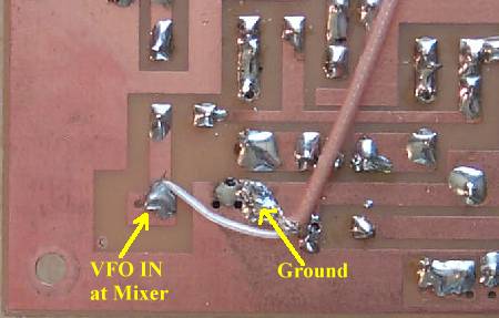 ____Miniature Coax Cable, cut a 12 1/2" piece (Bag 6), The coax is used between the VFO OUT in the upper left hand side of the board, to the VFO IN at the lower right hand side of the board. The coax supplied with the kit is Teflon 75 ohm cable. The best way to strip the insulation is to get a very sharp utility knife and slice a 1" section length wise, then fold over the cable and pull the shielding/center out of the insulation. Pull back the shielding slightly to loosen, make a small hole at the bottom, and pull through the center wire. Since it is Teflon, there is no danger of burning up the insulation on the center wire and causing a short while soldering. Pictures and Instructions for using the Teflon coax. (Click 'Back' on your browser to return here.)Best to mount this jumper underneath the board for a cleaner appearance and avoid interfering with the IR switching at the bandpass filters. When soldering underneath the board, solder to the traces and the ground plane. Saturate the ground braid with solder first, then solder the braid to the ground plane. Next solder the center wire to the output(VFO OUT)/input(VFO IN) pads. |
Making and soldering the 'XTAL FILTER OUT' coax cable____2 - Wire Loops, Install 2 wire loops at the Xtal Filter Out and Ground boxes as shown in the picture below. See Making Wire Loops for information on making them. Click Back to return. ____Miniature Coax Cable, cut a 10" piece (Bag 6). Strip and prepare as explained above. ____Solder the center wire to "XTAL FILTER OUT", solder the braid to the "Ground" box. Leave the other end loose at this time. 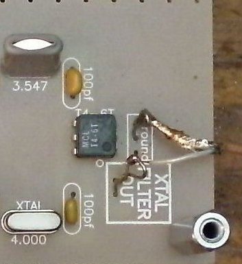 |
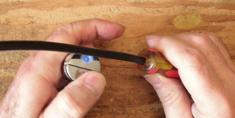
Fixing up the Shrink Tubing for the Photo Devices____1 - Lighter for heating the shrink tube - either butane (cleaner) or regular lighter |
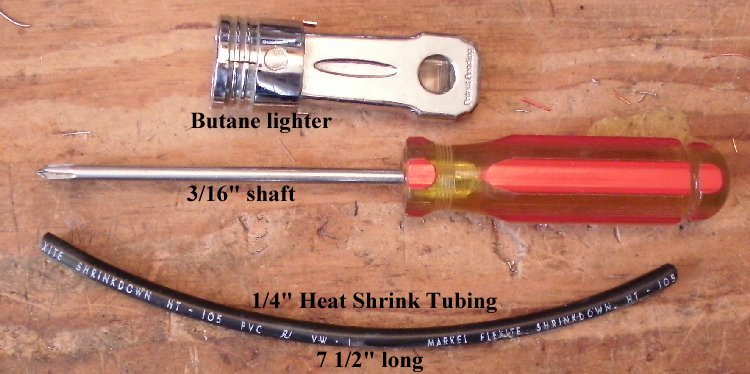
| Heat the tubing with quick sweeps. Mark how far you can go to the end of the screwdriver, go too far and it will collapse. Turn the tubing over and shrink the other half of the tubing. |
|
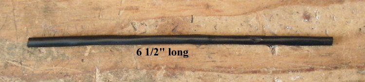
Cut the final length to 6-1/2". |
|
Install on the board. Make sure tubing is straight! |
|
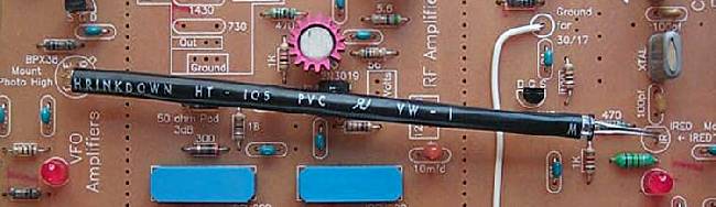
The following IR tubing pieces are used when the Vackar VFO is used: The 20/17 Bandpass Filter to VFO IR connection: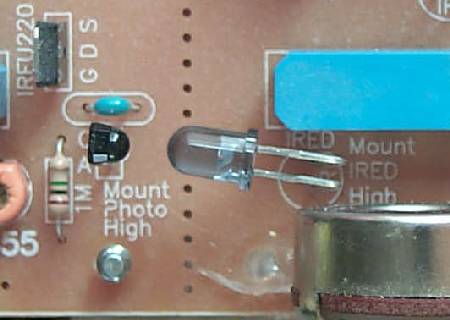 The picture below shows the tubing installed - about a 1 inch long piece. 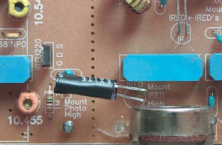 Crystal Filter to VFO Switching |
Crystal Oscillator to Crystal Filter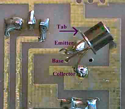 |
| The below shows the black tubing installed. |
Checking Your Work
____Place the PCB in front of a bright light. If you see light shining through any of the soldering holes, you missed a solder connection. |
Send E-Mail || Amateur Radio Receivers || Back to Instructions for the SuperLuminescent Receiver
