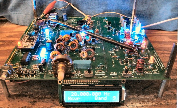
Bottom PlateThe following text describes how to put the receiver together as shown on the Home Page. If you have a problem when testing the boards, go to "LED Diagnosis/Troubleshooting" for help. A Bottom Plate is not needed unless you install a transmitter amplifier as part of the BLT and want to place it below the BLT. |
|
Instructions if drilled bottom plate is wanted with the kit. ____Using Board 2, since it has not been built, as a template, drill holes through a bottom plate sized 8-1/2 by 8-1/2" at the four corners. (Holes have already been drilled in the PCB material with most kits.)With the 6-32 size hardware supplied with the kit the holes need to be enlarged with a 9/64" drill bit. The holes are originally drilled for 4-40 size hardware. |
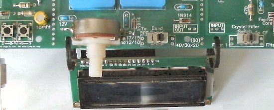
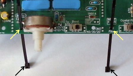
| The ties are run through the upper holes of the display and into the square couplers. |
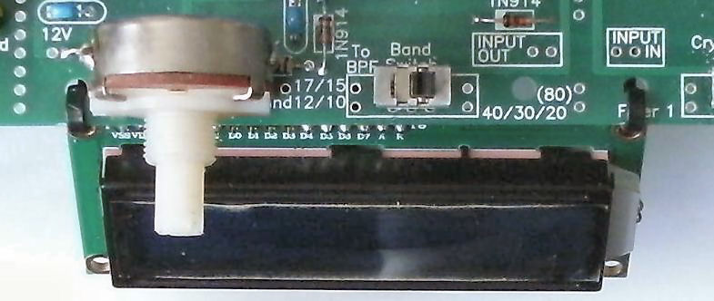
| Then the ties are tightened and the displayed is angled up for proper viewing. |
|
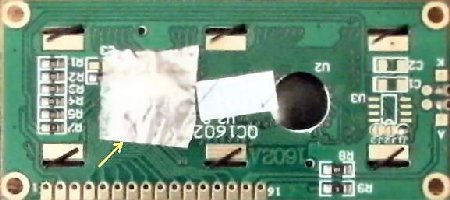
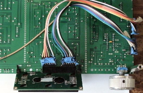
Attach the cables, Pin 1 to Pin 1 and Pin 16 to Pin 16. The masking tape on the cables on the right are labeled 1 and 16 to help get the cables on correctly. |
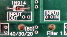
Testing Board 1____Be careful with polarity reversal. The 10mfd tantalums may explode and some traces may be burned going to the 7805 and First Mixer. Use diode protection if a mistake might be made in connecting the board to 12 Volts. ____Use a 1 to 3 amp diode, 1N4001 or similar at the 12 volt main connection (band goes to 12 Volt connection) to prevent accidentally hooking up the receiver with reverse polarity. The band of the diode is connected to the 12 Volt connection. Other end is connected to the power supply. A 3 amp diode is supplied with kit. If you are using a 13.8 volt power supply, use three 1 to 3 amp (supplied) diodes to drop the voltage to a little below 12 volts. The bands of the diodes are oriented toward the receiver 12V connection. The receiver works best at 11.5 to 12 volts. DDS VFO/VFO Amps/Bandpass Filter____Turn Bandpass Switch to 40/30/20 side. A mistake on the first prototype boards was made in the text, it reads 40/30/17. Later boards are correct.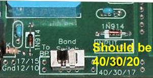 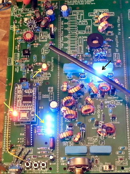 The DDS board LED should be on. The LED at the 1st VFO MOSFET amplifier should be on. ____The LED at the 40/30/20 side of the filters should be on. ____Move the Bandpass switch to the 17/15/12/10 side, the LED at the 17/15/12/10 filter should turn on. If the 40/30/20 LED at the Bandpass Filters is bright/dim, shield any light (overhead shop light, etc.) that is hitting the Photodiodes. The 40/30/20 LED should go out. ____Move the Bandpass switch to the 40/30/20 side, the LED at the 40/30/20 filter should turn on. If the 17/15/12/10 LED at the Bandpass Filters is bright/dim, shield any light (overhead shop light, etc.) that is hitting the Photodiodes. The 17/15/12/10 LED should go out. TroubleshootingBandpass Tuning Pot____Place a VOM in DC Volts position, and measure the voltage at the FILTER TUNE Bold circle (in the middle between the filters), and check its range while running the Filter Tune pot from end to end: +.12 to +11.7 Volts (within a volt).TroubleshootingFirst Mixer/Post-Mixer Amplifier____First Mixer: The LED on the right should be on. This LED shows the output of the DDS VFO and the proper functioning of the 2N5109 amplifier.To test this and show its function, turn the 500K trimmer at the 1st MOSFET amplifier counterclockwise and the LED should become dimmer or almost go out. Turn it clockwise and stop at the point right before the LED reaches maximum brightness. This adjusts the mixer drive for best dynamic range. ____VFO Post-Mixer Amplifier: The LEDs of the two Post-Mixer Amplifiers should be on. The reason for the different intensities of the LEDs is that they were different colors. They have a forward voltage drop of 1.7 to 2 Volts. Note: Do not put Super Brights in the Mixer or Post-Mixer amplifiers that have a 3.5 to 4 forward voltage drop. They will reduce gain considerably. 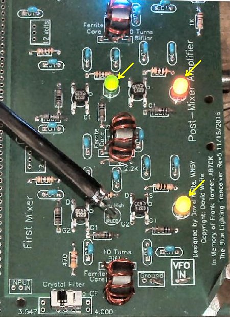 TroubleshootingCrystal FiltersThis is a special circuit that uses a series/shunt configuration to provide better isolation of the cyrstal filters than using two series LEDs. The bottom LED is the series LED and lets the signal pass to the filter which is ON. The top LED is the shunt LED and shorts the signal to ground for that filter which is OFF. The series LED of one filter is connected to the shunt LED of the other filter. ____Move the Crystal Filter Switch (front of board) to Filter 1. 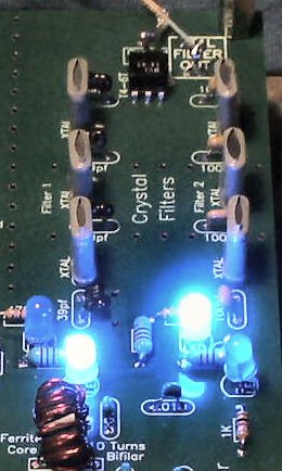 ____Move the Crystal Filter switch to Filter 2. 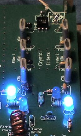 |
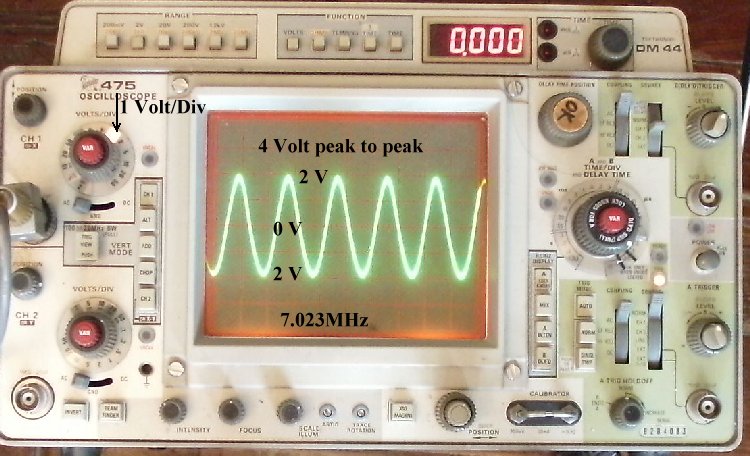
TroubleshootingAdjusting the 500K pot at the MOSFET Amplifier with the IR link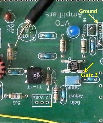 If you did the adjustment with the Mixer LED brightness above, you do not need to use the instructions below. If you have an oscilloscope, it is worth while to check it. You can run the mixer above the 4 Volt P-P suggestion. You will have more gain in the receiver and more output for a transmitter, if needed. Voltage AdjustmentWith Board 1 and the DDS VFO mounted and powered up, set to 40 Meters (7.000 MHz), measure the voltage between Gate 2 of the MOSFET and Ground. Adjust to 3.60 Volts with a Red LED, to 5.10 with a Blue LED. This is not a super critical adjustment, anywhere close will be fine. Is is important to do this measurement on 40 meters (7.000MHz) as the voltage on the other bands will vary quite a lot. With a OscilloscopeThe screen shows the output for 7MHz (4 volts peak to peak). The output remains fairly flat all the way to 28MHz. There will be a very slight drop at 24MHz to 28 MHz. Best sensitivity is at 8 Volts P-P, (set on 40 meters). This is the level set with the above instructions. Noise peaks should be heard on all the bands with a tuned antenna for the band. At 8 Volts P-P, you may see the sign wave be flat at the bottom, this is OK, just clipping in the mixer. The receiver has good gain down to 4 volts peak to peak with good noise peaks on 80, 40, 30 and 20 Meters, which is the setting for best dynamic range. However, for good noise peaks on the higher bands, an 8 Volt P-P (set on 40 meters) will have very good sensitivity on 17, 15, 12, and 10 meters. The only difference will be higher noise levels on the lower bands, because of the better sensitivity. The 8 volts P-P will drive any old boat anchor tube transmitter. With the modern QRP transmitters, you may need a pad to keep them from being over driven. A 6dB pad would be a good starting point if you don't have an oscilloscope to measure the drive from the receiver. With 50 to 100 Watt amplifiers, you might need a small amplifier to bring the output to the required 1 to 2 watts. This is sometimes a problem because finding a small amplifier with flat output from 40 to 10 meters is difficult. This problem is addressed in the transmit page with an MRF237 amplifier. |
|
|
|
If you have already built Board 2, then go to Mounting/Testing Board 2. |
Send E-Mail || Amateur Radio Receivers || Back to Ham Radio Instructions for the Blue Lightning Transceiver