
|
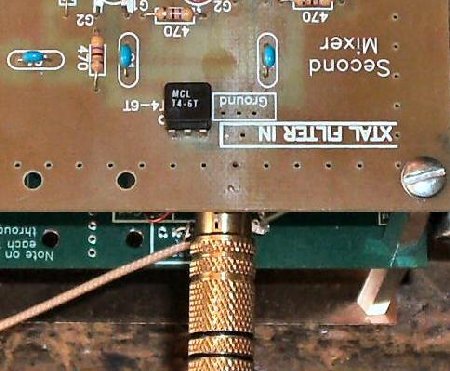
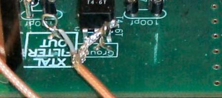
____Connect the 75 ohm coax that comes from XTAL FILTER OUT on Board 1 and connect it to XTAL FILTER IN on Board 2. |
|
At the Xtal Filter IN I used an RCA Phono connector. When doing a lot of testing, the RCA Phono connector made it very easy to move the board out of the way. Also, small coax cable can be soldered to the loops at both ends. Use a little extra length so the board can be flipped back out of the way when needed. |
|
____Connect the 12 Volt and the Ground BOLD squares on Board 1 to the 12 Volt and Ground BOLD squares on Board 2. |
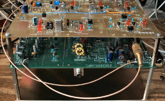
Connections to the Blue Lightning Transceiver____Connect the 12 Volt and Ground BOLD boxes on Board 1 or 2 to a connector for a 12 volt power supply. I used an RCA Phono connector at the side of Board 2 to connect power.(Connector not provided in the kit) Board 2 has a ground plane to solder on. 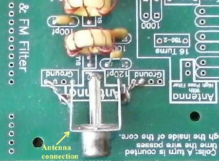 ____Connect the Antenna BOLD square on Board 1 to an Antenna connector. If a transmitter with an Antenna T/R switch is used (like the WA2EBY), the Antenna will be connected to the T/R switch. (Connector not provided in the kit) I used an RCA connector (and then an RCA to coax adapter on the antenna coax), but a 8 1/2" by 2 or 3 inch panel could be mounted on the back to the spacers to mount a coax connector. ____Connect the Speaker BOLD Square on Board 2 to a Speaker connector. A connector can also be soldered to the side or back of Board 2 on the ground plane. (Connector not provided in the kit)If the transmitter is placed on a bottom board, having the connectors for the 12V Power and Speaker placed on Board 2 makes more room for the transmitter and Low Pass Filters on the bottom board. |
|
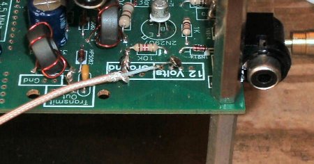
Shown above are the connections for the transmitter. Transmitter Out/Ground are on the left above and Key/Ground on the right for connection to a straight key, iambic keyer, or semi automatic key. Key is grounded to activate the T/R switch and the DDS VFO Key for elimination of the offset frequency. Shown above is a RCA Phono Jack that I soldered to the Key connection. Best to pre-tin the leads on the Phono Jack before soldering to the loops to get a strong solder joint. If you are using a 13.8 Volt Power Supply, three 2 Amp diodes are shown that drop the voltage to approximately 11.5 Volts for the BLT. I used a plastic tie to hold them in place, but any mounting is OK. |
Send E-Mail || Amateur Radio Receivers || Back to Ham Radio Instructions for the Blue Lightning Transceiver
