
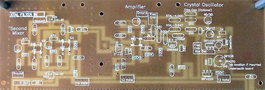
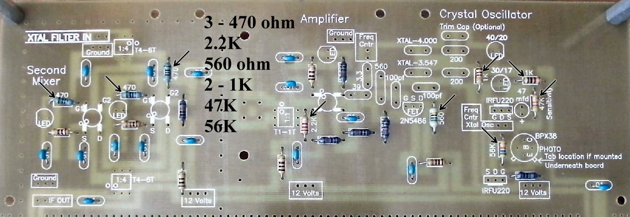
To learn about the Second Mixer, read the
Circuit Details - Second Mixer
before building this section.
To learn about the Crystal Oscillator, read the
Circuit Details - Crystal Oscillator/Amplifier
before building this section.
|
____Mount spacers on the four corners of the board to provide support for insertion of parts and easy soldering. 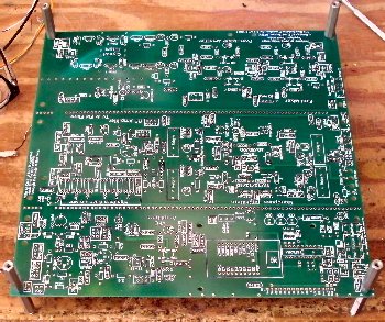 |
|
Insert all the components that have their values inside the footprint. They are the following: ____15 - .01 capacitors (Bag 3) |

|
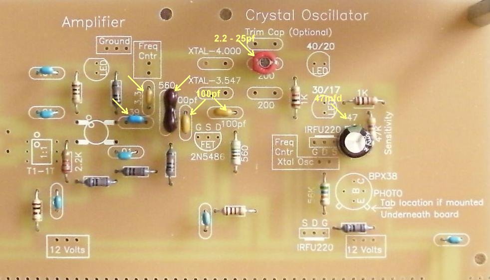
Solder Capacitors (Going left to right on the board):____2 - 100pf NPO (Bag 3), Located at the left side and above the FET (2N5486). Orange color, short leads flared out, labeled "101". |
|
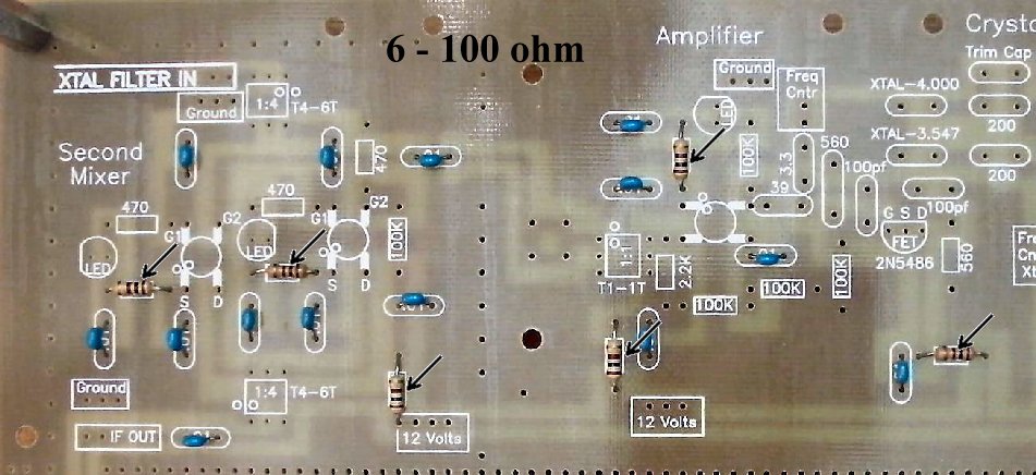
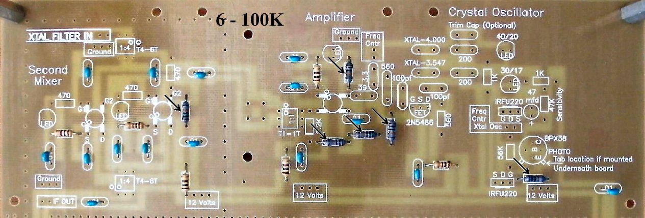
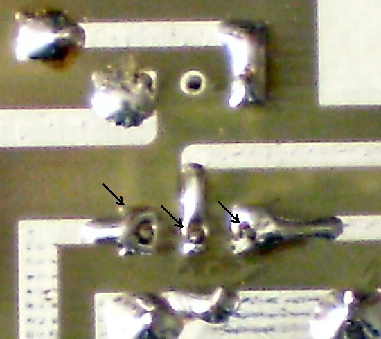
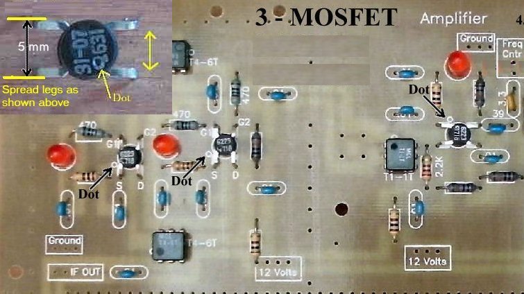
Double check your soldering to make sure you make a good solder With the bad solder joints below, the LEDs in the mixer did not light up when power was applied. |
|
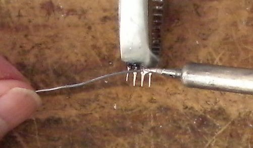
Solder A dot is placed outside the footprint so that you can double check your placement after it has been soldered to the PCB. The leads on each side of the part need to spread apart slightly to fit the footprint. |
|
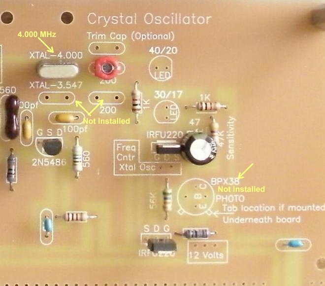
Solder Crystals____1 - 4.000MHz crystal (Bag 4), The markings are "RXD MP49 4.000 TaiWan A7" or "EA0380J 4.000 0640A". |
|
Solder Double Checking Your Work____Check the dot on the MOSFETs and the Minicircuits transformers. |
|
|
Send E-Mail || Amateur Radio Receivers || Back to Ham Radio Instructions for the Blue Lightning Transceiver
