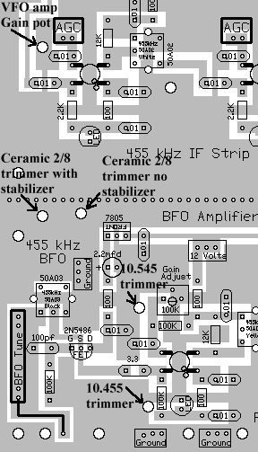

First, check the VFO frequencies. The picture above shows the access holes to reach the trimmer caps through the 2nd board. Picture A screwdriver with a 1/8" shaft 2-1/2" long with a small tip will reach the trimmers. The tip of the screwdriver will need to be modified. See "Picture of Modified Screwdriver" for instructions. If you lift the upper board, remember to do a test fit to see how much the VFO is offset, so that you can account for the difference before final assembly. ____Set the Bandswitches to 30 or 17 meters (both LEDs off at the VFO) and check the VFO frequency for 14.068 MHz (or 14.066 MHz) with Board 2 installed. ____Remove power and lift off Board 2, choose and execute your method of securing the VFO toroid - the best being melted wax. ____Pour melted wax from a common household candle onto the toroid and ferrite core for maximum frequency stability. Picture ____After the wax has cooled, recheck the 14.068 MHz (14.066 MHz) freqeuncy. TroubleshootingSecond, set the BFO frequency, peak the 455 KHz IF Strip, and adjust the BFO Amplifier.Set the BFO Frequency____Connect a 40 or 20 meter antenna to the receiver. Note: If you do not get a rushing noise out of the receiver, the first place to check is the BFO. It is very easy to accidentally ground the BFO tuning capacitor. Click here for diagnostic information. TroubleshootingPeak the 455 kHz IF strip____Adjust the "Filter Tune" pot on Board 1, until you hear a noise peak. Both 40 and 20 meters have very good peaks that can be found on the clockwise side of the Bandpass pot past middle position.____Readjust the BFO 455 KHz IF can where you hear the band noise and set to zero beat with the BFO cap half meshed. ____Go back and forth between the two adjustments, if need be, to get it right. ____Adjust the BFO tuning cap for one of the sidebands, at a higher tone than zero beat. ____Peak the first two 455 KHz IF cans on the 455 KHz IF Strip for best reception/noise. The white core will be 3/4 turn down from the top (first IF can). The yellow core will be two turns down from the top (second IF can) (approximately). The peak is not real sharp, but is easy to define. ____Run the core all the way up on the third 455 KHz can next to the AGC detector. There is tons of gain here, and it should not be adjusted for a peak until you start doing fine tuning on the receiver.TroubleshootingAdjust the BFO Amplifier____Adjust the "Gain Adjust" trim pot at the BFO until the LED just begins to light. It should be at full brightness when the receiver is first fired up. The best setting for minimum noise is where it just begins to turn on. This is not critical at all and can be set where you get the best audio.____Run the core all the way up on the 455 KHz IF can at the BFO Amplifier, next to the Product Detector. There is tons of gain here, and it should not be adjusted for a peak until you start doing fine tuning on the receiver. TroubleshootingAudio Pre-Amplifier/Audio AmplifierUse a 4" or 6" 8 watt speaker (or larger) for best results. TroubleshootingThird, Adjust the S-MeterDouble check that you have installed the proper MTR1 and MTR2 resistor values for the S-Meter you are using. 50uA Meter Multimeter - Values shown on the Board. Please Note: Turning the Zero Adjust pot all the way clockwise will turn off the LEDs in the IF strip. The adjustment for the Zero Adjust pot will be near 3/4 of the way counter-clockwise. Dimming the IF LEDs will shut off the IF strip! See "Picture Showing Adjustments". ____Disconnect the Antenna from the receiver.____Have a clip lead connected to one of the Bold AGC boxes, the other end will be grounded at the appropriate time to help adjust the S-Meter. ____Adjust both the Zero Adjust and the Sensitivity trim pots all the way counter clockwise. The S-Meter should be reading almost full scale. ____Move the Zero Adjust trim pot counter clockwise until a zero reading is obtained. The adjustment for the Zero Adjust pot will be near 3/4 of the way counter-clockwise. Make sure the IF LEDs do not dim with this adjustment. NOTE! You may not get the S-meter all the way to zero until the Sensitivity pot is adjusted. ____Ground the AGC line with the clip lead, the S-Meter should be off scale to the right. ____Move the Sensitivity pot till full scale reading is obtained. ____Remove the clip lead from Ground. The S-Meter should be off scale to the left. ____Move the Zero Adjust pot counter clockwise until a zero reading is obtained. ____Ground the AGC line with the clip lead, the S-Meter should show full scale reading. Your S-Meter Zero and Sensitivity adjustments should be close to what is shown in the picture below. ____If more sensitivity is desired, turn the Sensitivity pot counter-clockwise until the desired sensitivity is obtained. Having a signal tuned in will make this adjustment easier. At the more sensitive positions, the S-Meter will read past full scale when the AGC is grounded. Readjust the Zero pot so that it reads zero at no signal.Troubleshooting |
Send E-Mail || Amateur Radio Receivers || Back to Instructions for the SuperLuminescent Receiver

