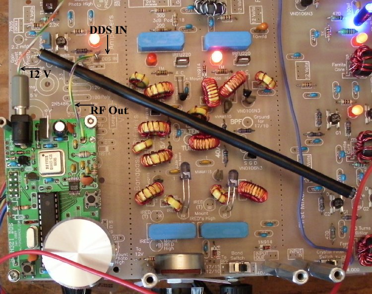
Frequency Counter A Frequency Counter, either your own bench Frequency Counter or the one you purchased with the kit, will help to test the DDS and transmit function. If you have purchased the LED Frequency Counter, this would be a good time to build the Frequency Counter kit. Go to Frequency Counter Construction page for instructions. After the kit is finished, short the "Osc In" to "Gnd" on the board so it will work as a regular counter. Use the "VFO In" and "Gnd" to make the measurements. This setup is shown in Step 12 of the Frequency Counter Construction. Testing the MOSFET amplifier LEDPower up the VFO board with 12 Volts at the 12 Volts and Ground connections. Cut a short length of black electrical tape. Install the tube over the front of the Phototransistor and the LED should light up. The gain of the MOSFET is controlled by the amount of IR light coming from the IRED at the First Mixer. The Phototransistor is triggered by normal light, but was used because of its high sensitivity to IR. Sensitivity peaks at 880nm. 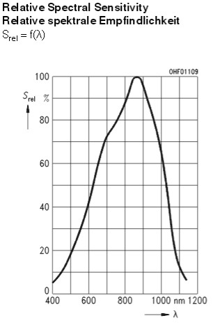 IR light lowers the Gate 2 voltage from 6 volts (or above) to near zero volts to adjust the MOSFET gain. IR lowers the resistance between the 'C' and 'E' pins. |
|
Side view - mounting holes for DDS match closely two holes on the VFO section of the PCB. However, this DDS is a 2009 version, which is retired, so I don't know if the board size is the same with the current versions. 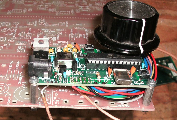 Picture shows connections to the 12 Volts and the DDS IN box which is the input to the MOSFET amplifier. 12 Volts and Ground connections could also be made to the 12 Volt and Ground boxes next to the 330mfd electrolytic at the top of the picture The Ground wire is not installed because the DDS is grounded with the mounting spacers by the ground plane on the bottom side of the PCB. 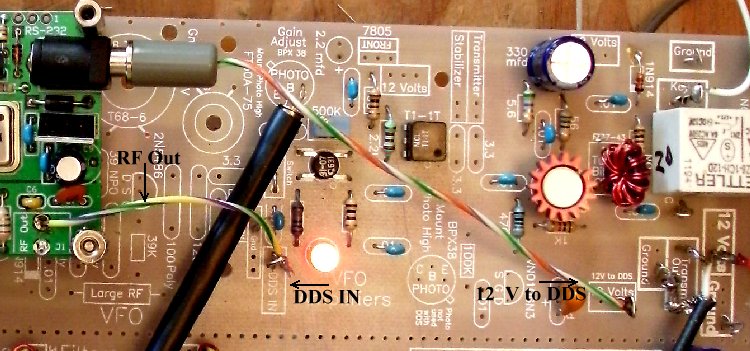 The LCD readout of the N3ZI DDS and the receiver kit LED readout. Receive frequency is on the left and the frequency applied to the receiver mixer with the offset is on the right. 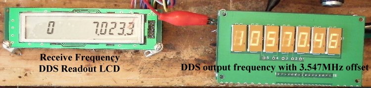 The output at the 'VFO OUT' should be checked with a scope. Shown below are the probe connections to the 'VFO OUT' and 'Ground' boxes. 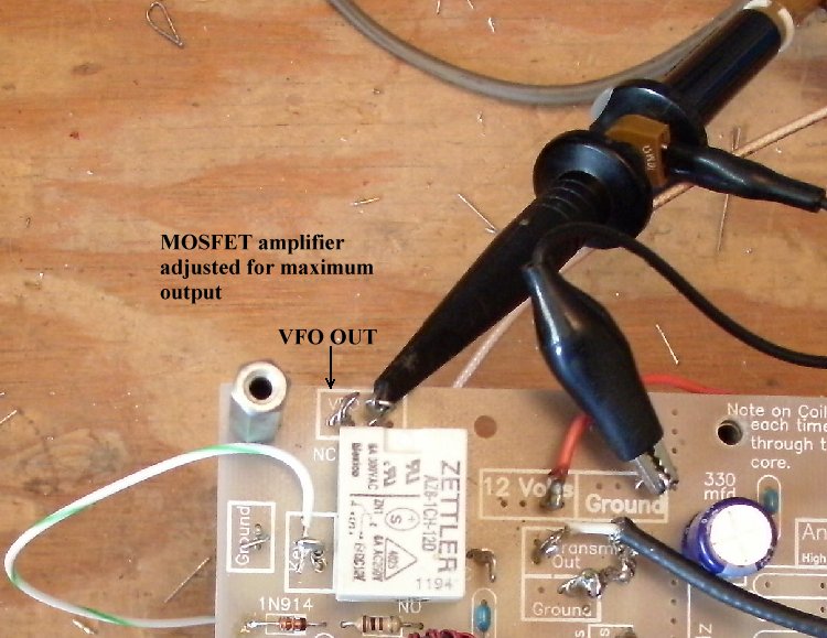
The screen shows the output for 7MHz (4 volts peak to peak) and it remains fairly flat till 21MHz where it drops to 3 volts peak to peak. This is because the 2009 version was designed for operation only up to 20MHz. Later verions (2011 and up) allow operation up to 34MHz. The receiver has good gain down to 4 volts peak to peak which is its setting for best dynamic range. However, below that it suffers somewhat in sensitivity. The 2011 and up version may not drop in output up to 24MHz, which is the highest output the DDS needs to reach to get 10 meters on this receiver (28MHz - 4MHz offset, however, it needs 28MHz output for the transmitter) The specs for the output of the N3ZI is 250mV. 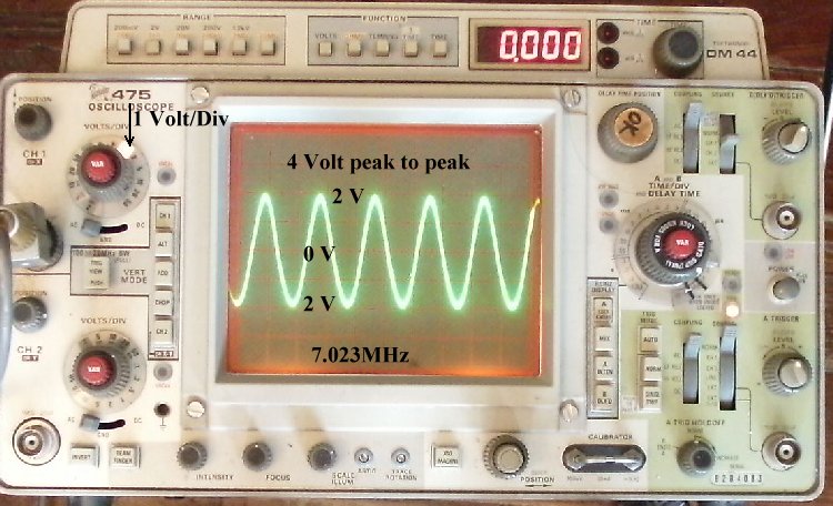
Programming the DDS for the transmit frequency is in the N3ZI instruction manual. It uses the RIT function which has fast switching which enables one to use it for a transmit switch.
|
|
No Output from the VFO The most likely problem is a mistake in the 2N5109 amplifier. Check unsoldered pins first and then for solder bridges. Check the Bifilar coil connections. Make sure there is continuity between the ends of the coil. You should read close to 12 Volts on Pin 'C' of the 2N5109 when power is applied to the board. If not, the coil was improperly wound. MOSFET VFO AmplifiersWhen the LED doesn't light at the MOSFET Amplifier, check for unsoldered or bad solder joints in that amplifier. 99% of all errors with the MOSFET amplifiers have been soldering mistakes. Place your finger over the Phototransistor, as light from a shop light will turn off the LED. The Phototransistor should be bent over and a piece of black tubing installed over the front of the part. If you need further help, go to Using the LEDs to Diagnosis Problems. This page goes into a lot of detail on what the LEDs show you when a mistake is made with a MOSFET amplifier. Relay does not turn ONThe relay is not getting 12 volts to the coil. The 'Key' terminal is grounded to turn on the relay. This puts the DDS transmit frequency to the 'Transmit Out' box for driving a transmitter amplifier. Follow the 12 Volt PCB trace from the '12 Volt' box next to the relay and make sure the relay pin is soldered to the trace. Also, check that the 1N914 diode is installed correctly (next to the relay), though it would have burned up and opened if installed backwards. |
Send E-Mail || Amateur Radio Receivers || Back to Instructions for the SuperLuminescent Receiver