

Xanax 1mg 360 $570.00 $1.58 $513.00
| Clinton | Xanax North Kingstown | South Carolina |
| Mars | Supply | Mount Pleasant |
| Wiesloch | Xanax Freystadt | Bobingen |
|
The VFO currently used in the receiver is a Vacker circuit shown below. To improve stability, a "Huff and Puff" stabilizer is used with magnetic coupling. |
|
This circuit is from "Meet the Vacker: The Simple, Stable VFO You've Been Looking For", By Mark L. Meyer, QEX, July 1997, Page 8.
One of the more interesting statements in the article was "Vacker developed a circuit decades ago that is simple and provides uncommon short-and-long-term stability without the use of fancy phase-locked loops or other control circuitry." (Page 8) The circuit, with the values shown, operates between 4.570 and 4.646 MHz. To change the values for the frequency you want, multiply the values by the ratio of your desired frequency to 4.570 MHz. "For example, if you wish to have a frequency of 3.500 MHz, you multiply C1-C7 and L1 by 1.3 (4.57/3.5) Frequencies higher than 4.75 will result in a multiplier value less than one." (Page 8) Q1 is a MPF102 or a 2N5486. One of the interesting things I discovered was that my 2N4416's would not work in this circuit. My suggestion is that if the circuit does not oscillate, try different FETs that are in the junk box. I like the 2N5486 over the MPF102 because the 2N5486 has proven to be more frequency stable than the MPF102. C8, C9 and C10 are used as compensation capacitors for the variable-capacitor diodes and have a negative coefficient factor. If you can't find these, use the emitter-base of a 2N3904 as a temperature compensator for the varactors. Shown below is a modified circuit showing the 2N3904 circuit.
 C1 and C2 should use parallel capacitors to aid stability (circulating currents are shared) and be NPO, C0G, or polystyrene capacitors. C8 serves a dual purpose. If it is a negative coefficient capacitor, it helps compensate the tuning diode, but it also isolates the DC tuning voltage from the rest of the circuit. The tuning diode can be of any value or type. Usually the MV21** series are used or the MV1662 recommended in the article. Also, high voltage rectifiers work well as tuning diodes. The article shows a very simple printed circuit board layout, but using 'dead bug style' has worked great and is recommended. |
|
The important capacitors are the poly caps (C11, C12, C13, and C14). Other values should be split in a combination to give 220pf and be poly to provide the best stability. The C3 trim cap is used to set the VFO frequency to 10.455 MHz, along with C7. The reason for the large value of C3 was the receiver was first set up for 40 and 20 meters, and C3 was used to set the frequency to 10.455 MHz (20 meters) or 10.545 MHz (40 Meters). C3 is a panel mount capacitor that was originally used as an antenna trimmer in the HQ-140-X. Approximately 17pf of C3 is used to set the frequency to 10.455 MHz. C15 is used to restrict the tuning range to 100 kHz. It value can be changed to effect the bandwidth to the desired range. The sharp filters preclude the reception of SSB, so 100 to 150 kHz was all the bandwidth that was needed. The reason for the multitude of NPO capacitors was to help stability, so circulating RF currents would be shared to help stability. Different values can be used as long as they add up to the same values in the schematic. C9 and C10 should be the best NPOs that can be obtained. They are critical for good stability. Any drift in these caps has a huge effect on VFO frequency. Again, different values can be used, as long as the total capacitance is the same. C16 is one section of the original main tuning capacitor of the HQ-140-X. The VFO is placed in the metal box with the main tuning capacitor. This box, along with the cabinet of the HQ-140-X, provides a very stable temperature environment for the VFO. L3 is 18 turns #20 wire on a T68-6 toroid cord. A ceramic coil form can be used, or even a self supporting open wire coil. A T80-6 or T68-6 provide better stability than a T50-6 core and are easier to wind. If a "Huff and Puff" stabilizer is used, wire size should be reduced to #24, to help the relay used with the stabilizer have the maximum range possible. See the Electoluminescent Receiver section on the Tramadol 50 mg over the counter for more information. L2 can be any value close to 200uH. But it should have good thermal properties to help with stability. I wound my own RF choke on a FT50A-75 core with 7 turns, which is a value a lot lower than 200uH, but a large core helps stability. With an FT50-43 core, wind as many turns with #24 or #22 wire that will fit. A molded choke cannot be used for L2, because if one of the trim caps is shorted to ground while adjusting the VFO, it will blow a molded choke (welding the wires together - losing its choking ability) and then blow the 2N5486. Both the RF choke (L2) and the toroid (L3) should be covered with wax from a household candle to keep air from reaching the cores. Metallic substances absorb temperature changes faster than the poly caps and you will lose the balance of the positive and negative temperatue coefficients of the different parts. The wax also provides excellent mechanical stability. L1 and C2 can be any value. They help with the isolation of RF currents from the VFO to the 12 Volts bus. C1 (2.2mfd) is a standard value used at the output of three terminal voltage regulators to keep the regulator from oscillating. |
|
The credit for this circuit goes to Buy 30 mg adderall online, who developed the circuit after my suggestion that magnetic coupling would work with a frequency stabilizer. It uses a shift register (74HC4517) as a memory for the stabilizer and provides excellent stability. At the present time, it is in the experimental stage and is being used with this receiver to evaluate its performance. So far, it has worked very well. One problem that has surfaced at times is that the output transistor (TIP121 - used as the relay driver) can get warm and start to drift. This causes the stabilizer to lose lock and will quit working. A transistor with a plastic case, also in a TO-220 (see schematic) package, is being used that shows better resistance to warming up than one with a metal heat sink. The output transistor has to be grossly overrated for the current supplied to the relay to prevent the transistor from warming up and causing an increase in current to the relay. Relays with coil resistance higher than 200 ohms work best. A coil resistance of 120 ohms or similar draw a lot of current and it is harder to keep the transistor cool. A Power MOSFET would not have this problem of increasing current with heat, but I have not been able to get a power MOSFET to work. I'm sure that one could be made to work, but so far my efforts have not hit on the magic solution. For those that don't want to build this circuit from scratch, I offer a stabilizer kit using a circuit developed by Klaas Spaarjaren, PA0KSB, the inventor of the "Huff and Puff", for $20.00. See the Electroluminescent Reciever section on the Frequency Stabilizer. This circuit has been used for many years and is time proven. The performance between this circuit and the one above is hardly noticable. |
Other Good Quality VFO CircuitsWhat follows here are descriptions of three different VFO circuits. The FET, a transistor low-noise design, and the NE602 used as a VFO. I have built and used them all except the transistor low-noise design. My favorite is the NE602, which I use in almost all my equipment where I need a 10 to 14MHz VFO. I have the FET at 10MHz in two receivers and it works great. I plan to experiment with the transistor low-noise design extensively, as it appears to be a really neat design. Just choose the one you have parts for, or try a new design you haven't tried yet. They all work great. A CMOS buffer can follow a VFO for a square wave signal into a diode mixer. "A CMOS Buffer For VFO's" will convince you to take the trouble for a square wave.
FET VFO Oscillators
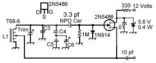 This circuit comes from the Progressive Communications Receiver that is in most of the recent ARRL Handbooks and the article "A Progressive Communications Receiver", by Wes Hayward and John Lawson, QST, November 1981, Page 11. C4 and C5 are adjusted in value so that C6, of almost any value, can be used in this VFO. The formulas for calculating the proper values are on page 21 in the November 1981 of QST. Working without the fo |