

|
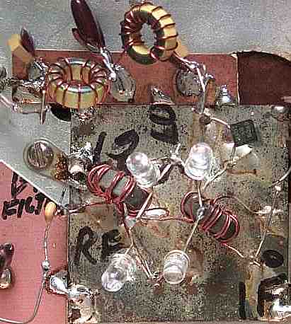
This is the current mixer used in the Super Receiver. This mixer was inspired from the suggestion of Pascal Nguyen, from Australia. He presented this mixer as a term paper in a University he was attending. In an email Pascal said, "My suggestion is to replace the mixer with passive led type. Please find more information from US patent 6,111,452. It is a wideband gap SIC material, it means high mobility for electrons. Simply speaking it is a ring diode mixer with all diodes replaced by blue leds. I built this type of mixer in 1998 but only with red led to convert my 500 kHz to audio." In a follow up email he stated, "...it was designed for High IP3 and jamming warfare by the US forces. I like mixer, the idea of using more than 2 volt of oscillation to turn the led on and off occurred to me in 1998, but unfortunately the red led is able only on very low frequency, I did not have high speed led in that time." For a copy of Pascal's paper, download this .pdf file, High Level Mixer. |

|
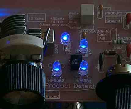
Needles to say, it worked! I found drive level to be dependent on frequency. The higher the frequency, the higher the drive level required. The LED mixer would work with just enough drive to light the LEDs. They did not have to be as bright as the picture above to work. When the LEDs were off, there was no output, but even with the slightest indication of light, the mixer would have output. It did seem to have more loss at lower brightness levels, with the higher brightness showing no difference in loss compared to a commercial mixer. Measurements with a Spectrum Analyzer will be made and posted at a future date. In the Super Receiver, an amplifier with two MOSFETs amps and one 2N5109 amp, provided enough gain to drive the mixer.  At 455 kHz, only one MOSFET amp was needed to drive the mixer. At 455 kHz, it seemed to have a cleaner output than the quad diode mixer it replaced. The image is the modification made on the Electroluminescent Receiver Kit. All the coupling caps between the BFO/amplifier, and the amplifier/mixer were raised to .01s to provide the highest drive level possible. It worked great! The HP5082s were clipped out, leaving the leads, then the super-bright blue LEDs were soldered to the leftover leads. Remember, the flat side of the LEDs go to the same side as the band side (cathode) of the diodes. |
|
|
Send E-Mail || Amateur Radio Receivers || Super Receiver || Super Receiver Circuit Details
