 Receiver Modifications
 Novice/Boat Anchor Transmitters || QRP Transmitters || 50 to 100 Watt Transmitters
Lowpass Filters
Switching and Driver Circuits || Pi Resistor Pads || IRED(T)s in the Bandpass Filters
Links
Receiver Modifications |
An SPDT relay is mounted at the end of the VFO section which is keyed at the same time the DDS VFO is keyed to eliminate the offset to give the correct transmit frequency. Two diodes are used to isolate the keying of the relay and the DDS VFO. The bands of the diodes (1N914, 1N4148 or similar) are tied together at the bands and mounted on a socket of the builders choice or whatever is demanded by the keyer used. Instructions for this are included in Mounting the DDS VFO and Testing. One of the Anode sides of the diodes goes to the Transmit Relay (Ground is needed to activate the relay) and the other anode goes to the DDS VFO "KEY" connection. If you are using a different DDS VFO, check the documentation of your DDS for instructions on keying the offset function. |
|
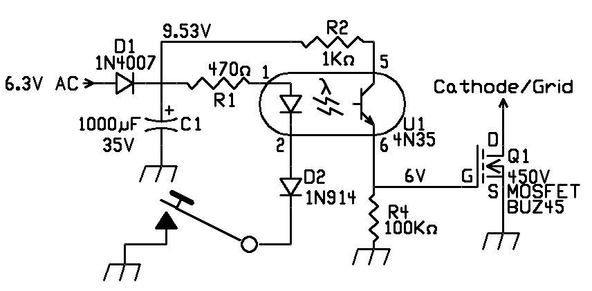
The circuit is built on a small prototype board. A 1" to 1-1/2"spacer is installed on one of the screws holding a terminal strip down and the board screwed on the top of the spacer. The MOSFET can be any type that is rated for the voltage used in the grid (grid block keying) or cathode (cathode keyed) circuit of the transmitter. A BUZ45 (rated at 450V) was used here because it was the first one found in the junk box. Grid block circuits use little current, so a much smaller MOSFET can be used that has the required voltage rating. The optoisolator can be any type similar to the 4N35. The circuit only uses 10 to 20ma, so it will not load down the filament circuit. The MOSFET is a voltage controlled device, so uses only about 1ma through the 100K resistor to switch the transmitter on. |
|
The QRP amplifier, with the large heat attached (top right), is the DLQRP power amplifier sold by the German QRP club. This amplifier can put out a maximum of 10 Watts and has worked very well. Very rugged as I have unintentionally tried to destroy it and never was successful. 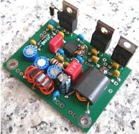 The output of the receiver (a 2N5109 amp) is enough to easily drive a QRP amplifier between 5 to 10 watts. I used the QRPproject QRP-PA 2008 single balanced MOSFET kit from Germany. It produces equal output from 80 to 10 meters and is very stable. it is very easy to build. The only negative is that you have to supply your own heat sink for the MOSFETs. The MOSFETs are mounted so they can be screwed to the back of a case for heat sinking. The link to the project on the web is the following: The SLR has about .1 watt output and the DLQRP amplifier only requires 10mW to get 10 Watts out. So a resistive Pi pad is needed between the SLR output relay and the DLQRP. Resistive Pi PadsA 3dB pad is shown above, but up to a 10dB pad has been used to lower the output to 2 watts. A 6dB pad would be a good starting point for 5 watts. The bias of the MOSFETs can be lowered from the recommended 120ma to lower the output also. |
|
The 10 watt non-inductive 50 ohm resistor was used to help lower the output to drive the WB2EBY 50 Watt MOSFET IRF510 amplifier with 2 watts. Helps stabilize the amplifier chain too. Antenna Relay CircuitsThe antenna relay, as shown above with the Boat Anchor project, was used here to control the T/R switching. See the Boat Anchor project for detailed information on this circuit. Schematic below: |
|
At the phono jack labeled 'To Keyer', you can see the isolation diodes going to the antenna switch, transmit relay on the SLR, and the DDS VFO. At the time of this build, the diodes for the transmit relay and the DDS VFO were not on Board 1 of the SLR. |
|
The RF T/R switch is easier to build and is a variation of the WA2EBY RF T/R switch. To make it trigger with the .1 watt from the receiver transmit relay, change R1 to 1 Meg. This increases the sensitivity of the T/R switch. Go to higher values (up to 10 Meg) if necessary. This circuit eliminates all the extra wiring for the keying circuit. Low Pass FiltersThe Low Pass Filters were built on another board. The Opto Band Switching in the picture above was used to switch the filters. Three filters were used: 40/30, 20/17, and 15/12/10. A IR LED in a 10um optic cable holder (Blue colored) was left on all the time, with about 20ma current (470 ohm resistor to 12V), and the cable was switched to the needed IR receiver (Black colored) at the Low Pass Filter board. The LEDs seen on the far right sticking out from the Opto Switching board showed which filter was being used. With no cable in the Black opto receivers, the 40/30 filter (Red LED) LED was on. When a cable was inserted into either of the Black receivers, it disconnected the 40/30 filter and turned on either the 20/17 (Blue LED) or 15/12/10 (Green LED) filter. In the prototype state that the build was in, it was easier to do this then wire up a lowpass filter switch with all the wires, etc. The optic cable is immune from RF and could be laid anywhere and provided great isolation between the transmitter and filters. For the circuit diagram and information on the IF emitter/receiver and cables, go to IRED(T)s in the Bandpass Filters. |
|
This kit is produced by "Kits and Parts dot Com" and is the Universal 5 Watt QRP Amplifier for $19 I have tested this kit with the transmitter and it works well. It has a 10K pot in its pre-amp to set the gain and can be moved to a front panel control. The kit puts out approximately 5 watts out on 40 and 30 meters, about 3 watts on 20 meters, and 2 watts on 17 meters with this transmitter setup. You do not need to build an outboard driver for this kit as it has a 2N2219A driver built in the kit with a gain adjust pot as mentioned above. Just connect it to the Transmit Relay output of the receiver. His instructions for winding the toroids are excellent. |
|
This is a very inexpensive 5 Watt linear amplifier made from Just a Bunch of Transistors - hence its name JBOT. The web site is the following: http://www.phonestack.com/farhan/jbot.html A homebrew project deluxe from Ashhar Farhan, designer of the BTX20. Several hams have built this amp on the QRP-L list. I have not built the JBOT so can't say much about it. The receiver Transmit Relay output could feed the input of this amp and work OK. The amplifier requires one milliwatt of drive. A 6dB resistive PI pad is needed to lower the drive from the receiver. The pad helps stability too. The type of transistor is not critical - any Ft500 MHz transistor with the same power rating of the 2N2218/2N2219 would probably work. |
|
Above is the prototype version of a 50 to 75 Watt WA2EBY MRF510 Amplifier, MRF237 2 Watt amplifier, Lowpass Filters, RF Activated T/R Switch, and a 5 amp 12V to 24V convertor. It is mounted on a 8-1/2" by 8-1/2" aluminum plate 1/16" thick. The plate works as the heatsink for the two MRF510s. Holes for the spacers are drilled at the corners and is mounted above the SLR. MRF237 2 Watt AmpMost of the 50 to 100 Watt Amplifiers require 1 to 2 Watts of drive. Since the SLR transmit output is only ~.1 Watt, an amplifier will be needed to boost the output to the required one or two Watts, with flat gain from 40 to 10 meters. The output of the SLR is flat across the bandwidth of the receiver, 40 to 10 meters, but finding a one to two Watt amplifier with flat gain to 10 metes has been more difficult than anticipated. Of course, the GQRP-PA can be throttled to one or two Watts with flat gain up to to 10 meters, but it seems overkill and expensive to use the GQRP-PA for that purpose alone. In my research I came across a schematic for a MRF-237 amplifier, "The QRP Three-Bander", by Aack Lau, KH6CP, Oct. 1989, QST. Made for VHF frequencies, it was being used in a HF amplifier. It had an unusual pin out of having the metal case attached to the emitter. This meant that the case could be soldered to ground. Be careful when looking for it with a Google search, as the datasheets found had the wrong pinout - with the collector attached to the metal case - don't believe them! A 2 watt amplifier was developed using the MRF-237 with a very simple layout resulting from the fact that the emitter was soldered to the ground plane. A step by step build instruction of this amplifier can be found at MRF237 Amplifier |
|
Output was 2 Watts flat across 40 to 10 meters. A 3dB pad was placed at the output between the MRF237 amplifier and the WA2EBY amplifier making a stable 1 Watt driver. |
|
A 50 Watt amplifier I found inexpensive and easy to build Manhattan style was "A Broadband HF Amplifier Using Low-Cost Power MOSFETs, Part 1 and 2", by Mike Kossor, WA2EBY. It can be found in the QST archives. The following link shows how to build the amplifier using the Far PCB for the amplifier: A board set is also available on Ebay at the following site: HF-Linear-AMP-40-watts-as-by-Mike-Kossor-WA2EBY-Semi-Kit The filter board I never built because finding the rotary switch has been difficult. The design of the three filter set made it easier to build. But in both plsces above you have to order both boards. The picture below shows the Manhattan style 50 watt MOSFET amp with the lowpass filters and opto switching/relays. |
|
The picture below shows the PCB strips and pads used to mount the amplifier. I have built four of these and they all work well. You take the Template File and cut along the edges of the traces and pads with a utility knife leaving light cuts. This shows where to glue the Manhattan strips and pads. It helps to put the amplifier template file in a picture program and remove the ground plane. The following picture can be downloaded (left click, save image as). Be sure to size at 5-1/2" by 3". The cut out for the MOSFETs is the larger rectangle where it says 'Cut Out'.
This layout shows the location of the parts: |
|
The following picture shows the parts mounted on the Manhattan board. The ferrites are some surplus cores I had and they worked well. The smaller recommended binocular core (BN-43-3312) from KitsandParts will probably have better coupling. My output with this amp was within 10% of the published values in WA2EBY's article. KitsandParts sells a complete ferrite core kit. |
|
This T/R switch is a modified version of the T/R switch used in the WA2EBY amplifier. A 12 Volt or 24 Volt SPDT relay can be used. I used a 24 Volt relay because it was in my junkbox and had good sized contacts. |
|
The schemtic is simple to build and works very well. The picture above the schematic shows a deadbug version. It is driven by the MRF237 amp. A small 50 cable can be seen coming from the output of the MRF237 amp at the relay which drives the T/R switch. It is grounded at only one end at the T/R switch. 12V to 24V ConverterA voltage converter is needed when no 24V power supply is available. They can be ordered from Ebay or Amazon. A 5 amp power rating is needed. The WB2EBY uses 4 amps at 24V. The one shown is the LTC1871 3.5V to 30V step-up 100W convertor. It is a 'Step Up Boost Module Power Supply 3.5VDC up to 30 VDC (100W). This particular one is not noisy and has worked well. Others have tested and were noisy. They can be found on Ebay for $8.32 (6/16/2016). Amazon also carries them: DROK LTC1871. You can use 24V swiching power supplies, but be sure they do not need a standing load to start up - they must be self starting. I have needed to add additonal filtering and put them in a metal box to get rid of the noise. I have used parts from old computer power supplies to suppress the noise of these switchers. The best source of information on containing switching power supply noise is the following: I used KA7OEI's suggestions and completely quieted a 48 Volt switcher. Excellent information is on his site. |
|
This filter was designed and analyzed by the AADE Filter Design and Analysis software. The 40/30 Diplexer transmit filter below was designed by William Sabin, W0NYH, and published in QEX, July/Aug 1999, page 20. These are used to save the MOSFET's in case of high SWRs and to extend their life. With the WA2EBY, the MOSFETs are strained to their limit, and since the power output is highest on the 40/30 bands, the following filter is useful to help extend the life of the IRF510s. The article can be found at http://www.qsl.net/wm5z/qex199907.pdf. With only 50 to 60 watts ouput with the WA2EBY, I used T50-2 cores and worked out the number of turns with a Toroid progran, using either the "mini Ring Core Calculator", or any online calculators. Amidon has a good one: Amidon Toroid Calculator (Iron Powder). I have used the following filter with success and have never blown a MOSFET using it: |
|
The version below uses Standard Value capacitors. the 201pf's are 200pf, the 83pf is 82pf and the 393pf is 390pf. Looks same as plot below using a noise generator and a Spectrum Analyzer for testing. |
![]()
|
This filter was a design that came with Elsie, ham20.LCT, and modified by expanding the tuning width, "TuneW", until the VSWR at 18 MHz was 1.01. Of all the filters tried, this one turned out to be the best. |
|
This filter is a SVC design modeled in Elsie. See the January/February 2011 issue of QEX (Pg. 29), "Seventh-Order Unequal-Ripple SVC Low-Pass Filters with Improved Second Harmonic Attenuation", by Dave Gordon-Smith, G3UUR, for information on these filters. When using the WB2EBY MOSFET amp, second order harmonics are estimated at 30dB below the carrier. So by the numbers, this filter should have the second harmonic of 15 meters (42MHz) at least -40dB meeting the FCC requirements. The filter takes care of the second harmonics of 12 Meters (48MHz) and 10 Meters on its own. |
|
Shown here is a differential keying circuit if it is determined that it may help the keying shape when turning on the DDS VFO and the Transmit Relay. It is not used. The outputs are 12 Volt. The Transmit Relay and DDS need a ground. Another transistor or circuit revision needs to be added to get ground outputs. It is difficult to shape the keying with a DDS and a Relay. In QSOs with highly skilled CW ops, it has been noted that the keying is hard. Not objectionably hard, but enough to be noticed by a trained ear and readily seen with a scope. Some thought on this indicated that electronic keying of the output DDS signal might be able to shape the keying waveform to what is considered best practice. This means replacing the relay with an electronic switch that is capable of shaping the CW waveform. Q4 turns on the first and Q5 turns on some milliseconds later. D2 and D3 isolate the keying of the sections. |
|
This is an expanded circuit of the one shown above if you need to control other functions with the same timing and delay of the antenna switching. The 50K pot "Delay" is set for whatever delay is needed for comfortable CW operation. I did not use the 50K pot as the 1K gave me a second or two delay which was fine for moderately fast CW. I also changed the 10mfd capacitor (C63) to a 1mfd to get the one or two second delay. D7 diode isolates the keying of this section. Q17 provides 12 volts (Key closed) to whatever needs 12 volts to switch. With this transceiver, Q17 switches Mute (Board 2 IF strip), and the Antenna Relay. Q17 can be any PNP 1 amp transistor. A TIP30A, B, or C will work or any other TIP PNP low frequency transistor rated at 1 amp or above. I modified the output so I could send a + signal to a relay in a three port antenna switch. Placing the relay in the antenna switch helps keep an impedance "bump" to a minimum and isolates the RF in the antenna switch box. Q19 provides a Ground for any circuits that need a ground to switch. If a different setup is used this provides a built-in ground switch in case one is needed. |
|
The following drivers are not needed with the Transmit Relay output of the receiver, since the last amplifier of the receiver is a 2N5109 broadband amplifier. They are included for information only. This circuit comes from the Solid State Design book and is in several ARRL Handbooks. A very generic, stable design used for receivers and transmitters. One of the best broadband low level amplifiers ever designed first seen in the Progressive Communications Receiver. Can't go wrong with this circuit for following a diode mixer or for stability in a transmitter amplifier chain. KitsandParts has a kit using the 2N5109 that equals this circuit for stability and amplification. Can be substituted for this circuit if you want to order a kit rather than 'deadbug' or Manhattan homebrew. Uses slightly different resistor vaiues than above. Another similar circuit using the 2N5109 is the "Low Band High Performance Preamp, by Larry, W7IUV". W7IUV spent a considerable amount of effort designing this amplifier. It does work up to 30MHz and designed specifically as an RF amplifier for the front end of a receiver. Uses precision resistor values and an additional resistor in the feedback circuit. An excellent paper well worth reading. Could be built on the KitsandParts kit.
Introduced in an post on the EMFRD Yahoo group but didn't seem to have the output of the previous circuits. Very stable and flat gain up into the GHz range. If you love to experiment, try it out. |
|
Here are the resistor pads used at the output of the driver. Having a 50 resistor pad at the input of the Final promotes stability over all kinds of building styles. Don't have to worry about critical shielding issues or layouts. Eliminates so many headaches - so to speak. Choose either the 3dB or 6dB pad for 5 Watts output depending on the output of your driver. Experimentation will be needed here to find the correct pad. Use the 8db pad for 2 Watts out to drive a 50 Watt amplifier. At a minimum I would use the 3dB pad even if you wanted maximum output from a 10 Watt QRP amplifier. |
|
In the ELR, Commercial IRED emitters can used in the IRED(T) footprints in the Bandpass Filters on Board 1. If you are mounting the transmitter separate from the receiver, this commercial pair of emitter/receiver and optical cable can to used to automatically switch the lowpass filters of the transmitter. They were used when four bands were installed in the ELR with two Bandpass filters, and two lowpass filters were used in the transmitter for the same bands, to automatically switch the filters in tandem. However, with the addition of 4 bands in the left hand filter (17, 15, 12, and 10) and three bands on the right side (40, 30, and 20), you would need more than two IRED(T)s to automatically switch the transmit filters with the receiver filters. In the SLR, one IR emitter is installed and is always on. An optic cable from the IR emitter is plugged into the opto IR receiver for the appropriate filter at the Lowpass Filter board. There are three filters: 40/30, 20/17, and 15/12/10. The 40/30 comes on by default with no optic signal. When the optic cable is plugged into the 20/17 or 15/12/10 optic receiver, it turns off the 40/30 and turns on the desired 20/17 or 15/12/10 filter. There are three Lowpass filters and two Bandpass filters used for transceive operation with the SLR. A rotary switch can be wired and used if desired. Depending on how the final receiver/transmitter is designed, either a rotary switch or optics will prove the most efficient. With careful wiring of a rotary switch, the approatiate lowpass filter could be chosen with the selection of the Bandpass filters in the receiver. A rotary switch wired to switch all the fiters would save time and trouble building the IR optical switching circuit at the Lowpass Filters. A third option, you could put the optic IR emitters on a rotary switch to switch the Lowpass Filters. This would use two IR emitters and two optic cables. The Bandpass Filters would be hard wired to the switches - only one wire needed. Ground the wire for 17/15/12/10, and leave ungrounded for 40/30/20. More on this later. Commercial Pairs w/1000µm Optical Fiber This pair of emitter/receiver and optic fiber is called the Experimenter's Kit IF-E10 in the Fiber Optics Kit section of Circuit Specialists web site. It contains a matched pair emitter/detector as pictured above and 1 meter of 1000µm optical fiber. |
|
Revisiting the WA2EBY Broadband HF Amplifier Jun 1988 - QEX (Pg. 8), Designing LC Filters Using SVC Filter Tables, By Ed Wetherhold, W3NQN Jul 1988 - QEX (Pg. 4), Designing LC Filters Using SVC Filter Tables (June 1988 QEX), (Feedback) Nov/Dec 2006 - QEX (Pg. 31), Seventh-Order Unequal-Ripple Low-Pass Filter Design, by Dave Gordon-Smith, G3UUR |
Send E-Mail || Amateur Radio Receivers || Back to Instructions for the SuperLuminescent Receiver
