|
Any DDS VFO will work with the SLR, but one that has a transmitter function (eliminates the offset with a 'key to ground') takes advantage of the keyed relay at the end of the VFO amps to drive a transmitter. The one addressed on this page will be the DDS VFO that is programmed for the SLR (the VK5TM simplified PIC-EL) which was modified to include the code to eliminate the offset when keyed. The N3ZI DDS, the later models (post 2011, I believe) that have a transmit switch using the RIT function and KD1JV's ATMEL XMEGA-A3BU evaluation board that drives a China DDS board will be shown on other pages when I have the time to describe them. |
Frequency Counter A Frequency Counter, either your own bench Frequency Counter or the one you purchased with the kit, will help to test the DDS and transmit function. If you have purchased the LED Frequency Counter, this would be a good time to build the Frequency Counter kit. Go to Frequency Counter Construction page for instructions. After the kit is finished, short the "Osc In" to "Gnd" on the board so it will work as a regular counter. Use the "VFO In" and "Gnd" to make the measurements. This setup is shown in Step 12 of the Frequency Counter Construction.
|
|
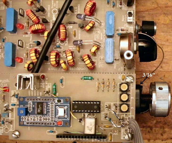
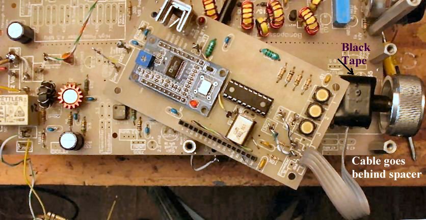
The picture above shows the final mounting of the DDS VFO. Follow the steps below to see how to get there. ____3 - 1" spacers and 2 screwsThe 1" spacers are mounted as shown above. The one in the bottom right hand corner screws into a male/female spacer that comes from Board 2 mounted below. The other spacers use a screw below them to secure to the board. Board 2 is mounted below Board 1 in this setup. Which works well because the LED Display and VFO tuning knob will be at a convenient level. |
|
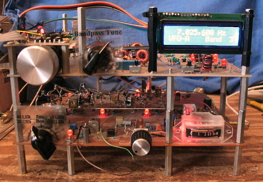
This shows the LCD mounted on spacers with plastic tie wraps. There are many creative ways to mount the LCD, but I will suggest this one which is easy The double male/female spacers used in the middle between the boards is not necessary. This is my working prototype and there is a dead bug noise blanker above the 455kHz IF for which I needed the extra room. And there is an extra spacer in front of the BFO amp used for some experimenting. The details to mount the LCD in this way follows:
The spacers used are double female 2-1/4" long supplied with the kit. If a transmitter is mounted above the receiver, these spacers are used at all the corners to support another bare aluminum or copper laminated board 8-1/2" by 8-1/2".
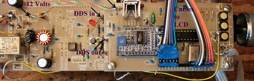
I used black electrical tape to provide some friction to help hold the LCD. If you don't like the appearance, you really don't need the tape. If you don't use the tape, the LCD needs a little black tape on the right hand side to insulate the wire going to the back light of the LED. See the picture below: 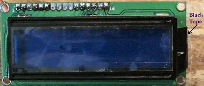 If you look on the side with the tape you can see the connections to the back light on the outside edge. 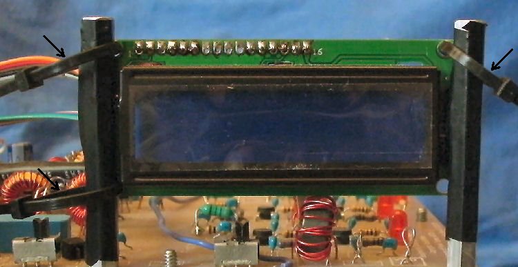 I used three ties, two on the left holes and one on the top right hole to secure the LCD on the spacers. The two on the left can be secured fairly tight. The spacer is pushed against the side of the LCD readout. Then wrap the long ends of the ties around to the back and tighten lightly - eyeballing it to keep it straight across and near to the top of the spacer. On the right side the end of the back light sticks out so you want the spacer to rest against the front of the back light against the LCD readout to keep the spacer standing up straight. A slightly loose fit will hold it up on this end and keep the spacer in front of the end of the back light. Then lightly tighten this tie. When satisfied with the mounting, cut the loose ends of the ties. 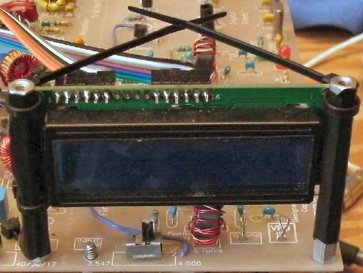 The finished mounting before cutting the loose ends of the ties. 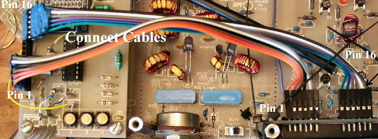 Connect the cables as shown above. There will be 4 open holes between the cables. Make sure to get Pin 1 of the LCD to Pin 1 at the DDS VFO, and Pin 16 of the LCD to Pin 16 of the DDS VFO. The Pins of the PIN 16 connector are bent over so the cable will reach between the LCD and the DDS VFO. Using the EncoderThe specifications for this encoder can be found at http://www.electro-nc.com/products/900index.shtml It has 128 pulses per revolution (PPR). When using this encoder, one must turn it slowly or the DDS VFO will jump in count to the opposite direction. The encoder takes a little time to get used to. Remember to turn it slowly. Using the digit up/down buttons (Switch 1 and 2) will get you were you want in a hurry. Efforts will be made to solve the jumping when turning it quickly. An updated chip will be shipped out when solved. However, the first issue being studied is to add an RIT function. Adjusting the 500K pot at the MOSFET Amplifier with the IR link.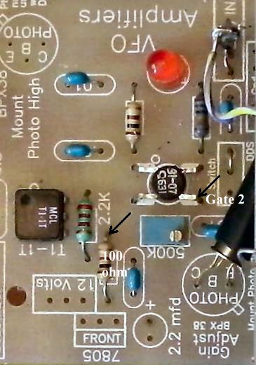 Voltage AdjustmentWith Board 1 and the DDS VFO mounted and powered up, measure the voltage between Gate 2 of the MOSFET and Ground. Adjust to 2.68 Volts. This is not a super critical adjustment, anywhere close will be fine. Resistance AdjustmentNo power is applied with this adjustment. The IR tube is connected. With the positive lead of the DVM on Gate 2 and the negative lead on the top of the 100 ohm resistor (as shown by the arrows in the picture above), adjust to 178K ohms. If the leads are reversed, negative on Gate 2 and positive on the 100 ohm resistor, resistance is 186K. With a OscilloscopeThe screen shows the output for 7MHz (4 volts peak to peak). The output remains fairly flat all the way to 28MHz. There will be a very slight drop at 24MHz to 28 MHz. The receiver has good gain down to 4 volts peak to peak, which is its setting for best dynamic range. However, below that it suffers somewhat in sensitivity. The 4 volts P-P will drive any old boat anchor tube transmitter. With the modern QRP transmitters, you may need a pad to keep them from being over driven. A 6dB pad would be a good starting point if you don't have an oscilloscope to measure the drive from the receiver. With 50 to 100 Watt amplifiers, you might need an small amplifier to bring the output to the required 1 to 2 watts. This is sometimes a problem because finding a small amplifier with flat output from 40 to 10 meters is difficult. This problem is addressed in the transmit page for the SLR. 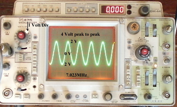
|
|
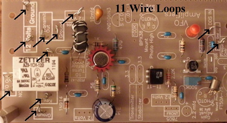
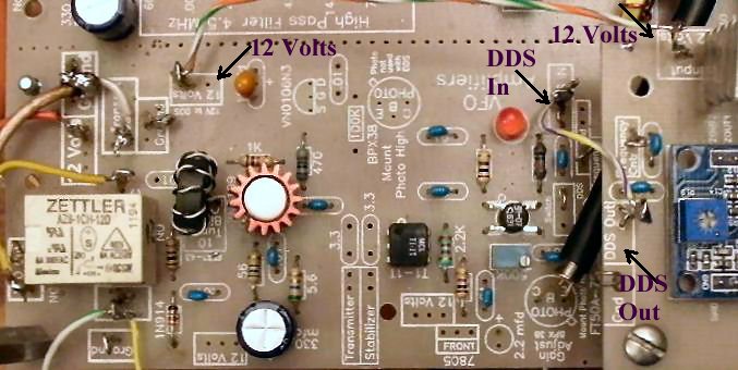
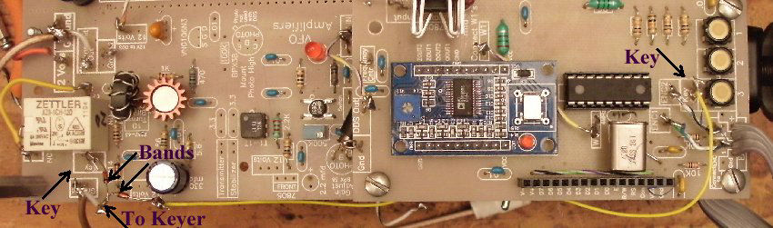
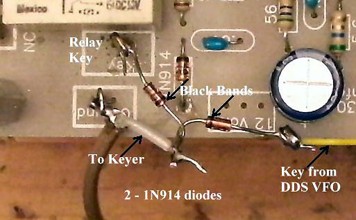
No Output from the VFO The most likely problem is a mistake in the 2N5109 amplifier. Check unsoldered pins first and then for solder bridges. Check the Bifilar coil connections. Make sure there is continuity between the ends of the coil. You should read close to 12 Volts on Pin 'C' of the 2N5109 when power is applied to the board. If not, the coil was improperly wound. MOSFET VFO AmplifiersWhen the LED doesn't light at the MOSFET Amplifier, check for unsoldered or bad solder joints in that amplifier. 99% of all errors with the MOSFET amplifiers have been soldering mistakes. Place your finger over the Phototransistor, as light from a shop light will turn off the LED. The Phototransistor should be bent over and a piece of black tubing installed over the front of the part. If you need further help, go to Using the LEDs to Diagnosis Problems. This page goes into a lot of detail on what the LEDs show you when a mistake is made with a MOSFET amplifier. Relay does not turn ONThe relay is not getting 12 volts to the coil. The 'Key' terminal is grounded to turn on the relay. This puts the DDS transmit frequency to the 'Transmit Out' box for driving a transmitter amplifier. Follow the 12 Volt PCB trace from the '12 Volt box next to the relay and make sure the relay pin is soldered to the trace. Also, check that the 1N914 diode is installed correctly (next to the relay), though it would have burned up and opened if installed backwards. |
Send E-Mail || Amateur Radio Receivers || Back to Instructions for the SuperLuminescent Receiver