

|
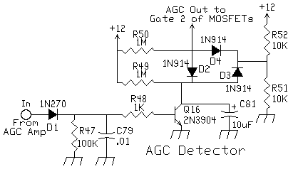
The basic idea for this circuit came from the "Progressive Communications Receiver" in most of the recent ARRL Handbooks. The circuit is in the IF section of the receiver.
The transistor can be almost any 2N2222/2N3904 type or substitute. The 1N270 is a germanium diode. Any germanium diode will work. If all you have are 1N914's, measure the forward voltage drop with a DVM (most of them have this function - the diode symbol), and use the one with the lowest reading. Your penalty is a less sensitive S-meter reading, but by an amount that you would hardly notice. The 1N270's run about .3 volt whereas the 1N914's run .5 to .7 volt. The two diodes connected to the 10K resistors, one going to ground and the other to 12 Volts, keep the voltage at both the collector of the transistor and gate 2 of the MOSFETs, at 1/2 the supply voltage, or approximately 6 volts. Both circuits are fed with 1 megohm resistors. The 1 megohm resistors and the 10 mfd electrolytic or tantalum capacitor set the response times. If you are going to use this circuit in another receiver, be aware that as the IF frequency increases, lower voltage is developed across the diode, capacitor (rectifier, filter) combination. It's harder to get AGC action the higher you go in frequency. One of the reasons for the 455KHz IF strip is to achieve a great AGC. At 455KHz, plenty of voltage is developed to have a fast acting, active AGC. According to Rohde, the best AGC is when the S-Meter is barely activated from the band noise level. That is achieved with this IF strip and AGC circuit.
|

Send E-Mail || Amateur Radio Receivers || Super Receiver || Super Receiver Circuit Details
