|
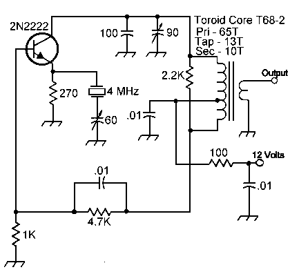
The tap on the toroid winding is placed 13 turns from the ground end of the winding. The 60pf and the 90pf trimmer capacitors are not critical values. Any trimmer from 40pf to 100pf can be used. A smaller capacitor with the coil (lower than 60pf) may require adding some turns on the toroid.
This crystal oscillator comes from the Progressive Communications Receiver. The reason for this oscillator is the savings in parts count. This oscillator has enough drive for a diode mixer, and does not need a buffer/amp.
Two of these are used in the receiver.
Output impedance is 50 ohms.
If you build this for different frequencies, look at the original article, the Progressive Communications Receiver (November 1981 QST & The ARRL 1986 Handbook) for component values for different frequencies.
The 90pf variable capacitor needs to be fine tuned after the oscillator is connected to the diode mixer. Tuning is fairly sharp. Sometimes it will not oscillate until it is tuned, so when first testing be sure to adjust the 90pf variable to get output.
The 60pf variable capacitor is used to bring the output of the two filters to the exact same frequency. This is best done after the receiver is built. Tune in a moderately strong signal, and switch between the filters till the signal is the same pitch by adjusting the 60pf variable capacitor on one or both of the oscillators.
Low Noise Oscillator

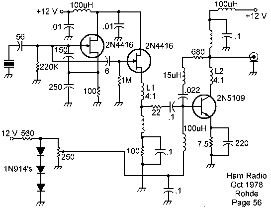
For those that want the best, this oscillator was presented by Ulrich L. Rohde, DJ2LR, in his article "Evaluating Noise Sideband Performance in Oscillators", Ham Radio, October 1978, Page 51.
Inductors L1 and L2 are 6 turns, center tapped, on 1/4-inch TC9 core. (FT37-43 will work great.)
The article states the above oscillator is a "suitable low-noise crystal oscillator circuit with a wideband postamplifier that delivers the required +17 dBm output level or slightly more. Any inductive-mode crystal between 400 kHz and 30 MHz can be plugged into this circuit and give useful output without any adjustments."
The following quote describes the performance of the above circuit and one he shows for using third-and-fifth-overtone crystals:
"The noise performance of the crystal oscillator circuits.....is better than 120 dB/Hz at 1 kHz from the carrier, and 150 dB/Hz or more at 20 kHz from the carrier. Because of their excellent noise performance, these circuits can be used as local oscillators without degrading receiver performance; very few oscillators and practically no frequency synthesizers achieve their low-noise sideband levels."
He warns against using the following circuit: "Probably the worst and noisiest of all oscillator circuits places the crystal between the transistor base and ground. The reason for the high noise contribution is that this circuit severely degrades the Q of the crystal. The noise sideband performance is partially dependent on the circuit but is determined primarily by the Q of the resonator: an LC circuit, a high-Q cavity, or a quartz crystal, and the latter has the highest Q of all known resonators."
References
Ulrich Rohde published an article "Designing Low Phase Oscillators" available in .pfd format at the ARRL web site. Subtitled "Find an oscillator design that ensures low phase noise using modern computer programs."
For every configuration of oscillators imaginable, check out "Crystal-Controlled Oscillators", Roger L. Harrison, VK2ZTB, Ham Radio, pp 10-22. Subtitled "A comprehensive review of many circuits with recommendations to help you choose the crystal oscillator best suited to your design needs."
|


