
|
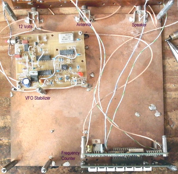
Notice that the spacers are two of the shorter male/female spacers screwed together. This gives the necessary height to mount the frequency counter. Note also the male ends are on top. The other longer spacers are female/female and need the male end to screw into. Screws are used on the top and bottom of the boards to secure everything. On the shorter board now supplied with the kit, the Stabilizer is moved behind the Frequency Counter with the connection to +12V at the back left. The picture above shows all the components placed on the bottom board. The power supply should be a well regulated/filtered power supply. Almost all wall warts have caused hum in the audio. The stabilizer is mounted underneath the VFO amps. A single sided PCB is included that is mounted on the bottom of Board 1 to shield the Frequency Counter from the First Mixer. See Shielding the Counter in the Frequency Counter instructions. Mount the shield after you have finished building Board 1. Connections to the Speaker and Antenna can also be placed on this board. Instructions for wiring the Frequency Stabilizer are at Connecting to the Receiver. Instructions for wiring the Frequency Counter are at LED Frequency Counter - Connecting to the Receiver |
Send E-Mail || Amateur Radio Receivers || Electroluminescent Receiver
