LED Frequency Counter
Connecting to the Receiver

LED Frequency Counter Connections for
the Brown Colored Boards Dated 3-14-2015

LED Frequency Counter Connections for
the Salmon Pink Colored Boards Dated 10-1-2005

LED Frequency Counter Circuit Details

Construction of the PCB
Connecting to the Receiver|| Using the Frequency Counter
LED Frequency Counter Parts List

Connecting to the Receiver

Crystal Oscillator Connections
Oscillator Frequency Connection || VFO Connections
Using a Rotary Switch
The 20/17 and 40/20 Connections || Connecting 12 Volt Power
Shielding the Counter
Using the Frequency Counter


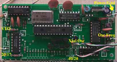
All the board connections labeled in yellow.

Small coax is used for the VFO and Osc Freq connections. Other connections are single wires.

The pictures for this section come from the first PCB version of the counter, but no changes were made in the second PCB that change what is said here.


Crystal Oscillator Connections
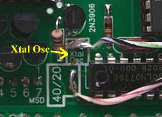
"Xtal Osc" connection shown on the Frequency Counter board.

The wire from the 'Xtal Osc' square is connected to the 'Freq Cntr Xtal Osc' box at the Crystal Oscilltor on Board 2 as shown above. There is a wire loop installed in the box where the wire is connected. It can be connected below the board if desired.


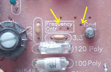
Oscillator Frequency Connection
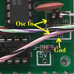
The Oscillator Frequency connection on the Frequency Counter PCB.
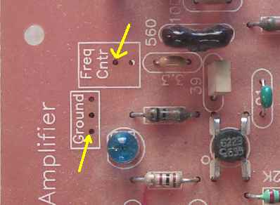
This picture shows the location of the connection for the "Osc In" and "Gnd" from the Frequency Counter. Connections can be made from the top or bottom as you please. Putting a wire loop in the 'Freq Cntr' and 'Ground' box make it easy to connect the coax.
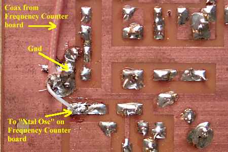
The connection shown made on the bottom of the board. It is a lot easier to make the connections to the ground plane and "Freq Cntr" on the bottom side of the board.


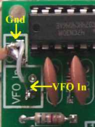
VFO Connections

The "VFO In" connection on the Frequency Counter PCB.

The place on Board 1 at the VFO for the "VFO In" and "Gnd" connections from the frequency counter board.
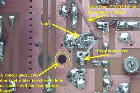
The picture above shows how the connections are made underneath the board. Be careful to leave enough room around the hole for the spacer to seat against the PCB.


The 20/17 and 40/20 Connections


The 20/17 connection on the Frequency Counter PCB.


The 40/20 connection on the Frequency Counter PCB.

The connections to the Bandpass Filter and Crystal Filter connections. The 20/17 and 40/20 labels refer to the side of the switches the wires are soldered.

The connections shown underneath the board. The 40/20 connection is by itself. The 20/17 is connected with an existing wire.

There are holes on the sides of the switch to make the connections or the wires can be soldered to the pads as shown in the picture.


Connecting 12 Volt Power

The 12 Volt connection on the Frequency Counter PCB.

Connect a piece of small coax to the 12 Volt and Gnd connections and tie into the same connections on Board 1 or at the back of the bottom board where you are making incoming power connections


Shielding the Counter

A shield is placed on the bottom side of Board 1 above where the counter will be mounted. The picture below shows the top side of a piece of single-sided PCB that is included with the kit when ordering the counter.

A piece of this single-sided PCB is sent with the kit when the frequency counter is ordered for shielding.

Shown in the picture is the easiest way to implement the PCB for shielding. This PCB board shields all the area above where the counter is mounted. Band noise, except a very quiet 17 meters, covers up all the counter noise.

The black arrows point to the connections to the ground plane of Board 1 of the ELR. Short pieces of bare wire are soldered to the PCB and then bent down to the ground plane of the receiver. NOTE: Double check you are soldering to the ground plane and not a trace!

Notice that the bottom of the board in the above picture is cut shorter than the top. This allows the board to be soldered even with the front of the board where the counter mounts.


Mounting the Frequency Counter

One easy way to mount the frequency counter is with solder lugs soldered to the PCB mounting board.

The holes on each corner of the Frequency Counter PCB can be used in any creative way to mount the counter.

A close up of one of the solder lugs.

When 220 ohm resistors are used to connect the boards, the back PCB of the frequency counter can be bent down to give as much distance from Board 1 of the receiver to help prevent/lessen birdies from the counter getting into the receiver.

The newer boards use headers to connect the boards. They cannot be bent down and are mounted in parallel. The shield provides enough shielding for good performance.

Using the Frequency Counter

The frequency counter will switch automatically as you switch the Bandpass Filter and Crystal Filter switches.

You will notice a slight delay (about 1-2 seconds) and see the frequency counter read the offset frequency. Then one second later will show the correct frequency for the band you have selected.

When powering up the receiver, depending on the band the receiver is on, there may or may not be a delay on the crystal oscillator frequency.

When turning the receiver on, off and then back on, wait five seconds or so for the delay capacitor at the crystal oscillator to fully decay. If you get the wrong frequency at start up, just switch to another band (wait for it to show the new band) and back, the frequency counter will correct itself.

Using a Rotary Switch

The installation of a rotary switch uses different connections than using the slide switches on Board 1. Skip the instructions "The 20/17 and 40/20 Connections" and go to Connecting 12 Volt Power after wiring the rotary switch. "The 20/17 and 40/20 Connections" instructions are for wiring the slide switches on Board 1.
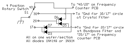
Depending on where you mount the Rotary Switch, you may want to make your connections to Board 1 on the copper traces underneath the board for a cleaner look.

Top connection coming from "40" switch contact:
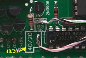
To "40/20" on Frequency Counter PCB.


The middle connection from the "30" switch contact (on Board 1, Section 3):
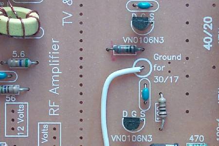
To Gnd for "30/17" circle at Crystal Filter


The two locations for the bottom connection:
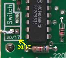
"20/17" on Frequency Counter PCB
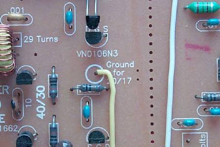
Gnd for "20/17" circle at Bandpass Filter


Send E-Mail || Amateur Radio Receivers || Electroluminescent Receiver || Back to Ham Radio Instructions
Back to LED Frequency Circuit Details || Back to LED Frequency Counter Construction


Last Update: 5/25/09
Web Author: David White, WN5Y Free Website Translator