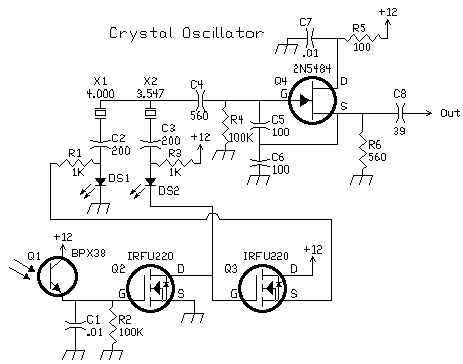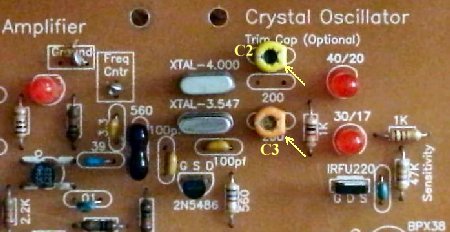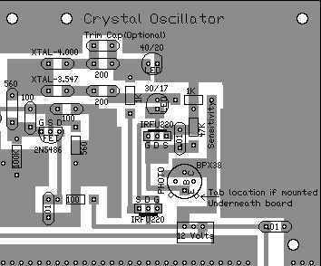


The oscillator frequency is switched with the crystal filters to maintain a 455 kHz output for the 455 kHz IF strip. If the 3.547 MHz crystal filter is on, the BPX38 does not receive any infra-red energy, and is turned off. When the BPX38 (Q1) is off, no current flows through Q1, the 100K resistor (R2), brings the gate voltage of Q2 to zero, turning off Q2. 12 Volts flows through a 1K resistor (R3), through the 3.547 crystal LED (DS2), which brings the gate of Q3 to 12 volts, which turns on Q3. No current is flowing, since the Gate of Q3 is very high impedance, so the 3.547 LED (DS2) is off. But Q3 is turned on, which supplies 12 Volts to the 4.000 LED (DS1) through a 1K resistor (R1), which yields an oscillator frequency of 4.000 MHz. If the 4.000 MHz crystal filter is on, the IRED emitter at the filter shines infra-red light on the BPX38, which turns the phototransistor on. When the BPX38 is on, the Gate of Q2 raises to 12 volts, turning on Q2. The source of Q2 grounded, so when Q2 is turned on, the Gate of Q3 is grounded, turning off Q3, which turns off the 4.000 LED (DS1). This also grounds the cathode of the 3.547 LED (DS2) and 12 Volts flows through the 3.547 MHz LED ((DS2), turning on the oscillator to 3.547 MHz. Modifications for a Single IF FrequencyThe Blue Lightning Transceiver will be using the same crystals in both Crystal Filters with DDS VFOs that can not be programmed for two filters of different values. In this case, the Crystal Oscillator will have to locked on to one mixing crystal to get the 455kHz IF. Below are the instructions for the crystal filters that can be used. Using 4.000 MHz Crystal Filters: Short C & E on the Crystal Oscillator Phototransistor - BPX-38 with a short jumper wire soldered between the leads underneath the board. This will lock the Crystal Oscillator to use the 4.000 side of the Crystal Oscillator. Using 3.547 MHz Crystal Filters: Put a piece of black tubing over the Phototransistor so no light reaches the lens. You have to block the front and back of the Phototransistor. Additional Circuit InformationThe 200pf capacitors (C2 & C3) are used to fine tune the frequency of the crystals, so that the BFO is the same pitch for both sets of frequencies. The 200pf capacitors get the pitch very close, but not exactly, so the BFO tuning capacitor is adjusted to maintain proper pitch when switching between the crystal filters.  The best tuning method found was to use low value small variable capacitors, ones with yellow or orange colors, in place of the 200pf capacitors as shown above. Optional One-crystal Filters The four unlabeled holes to the left of the amplifier is where the one-crystal filters are added. The horizontal traces between the holes need to be cut if the crystals are added. If the optional one-crystal filters are added at the oscillator amplifier output, the small value variable capacitors (shown in pic above) help tune the crystals so that maximum energy passes through the one crystal filter. The brightness of the LEDs at the mixer show oscillator output, so they can be used as an indicator to find the right values for C2 and C3 for maximum output through the one-crystal filters. The one-crystal filters remove the second harmonic content of the oscillator and provide a very clean signal to the second mixer. The filters also remove phase noise from the output. The passband of the one crystal filter is lower than the crystal oscillator's frequency, so the crystals must be lowered in frequency to fit through the filter with as little attenuation as possible. As mentioned above, the small variable capacitors of yellow or orange value worked best.  The output of the oscillator/amplifier chain, with the LEDs in place, is optimum with about 5-6 volts peak-to-peak into the mixer. The brightness of the second mixer LEDs are a direct indication of oscillator drive levels. |
Send E-Mail || Amateur Radio Receivers || Blue Lightning Transceiver ||
Infrared Switching Home Page

