
|
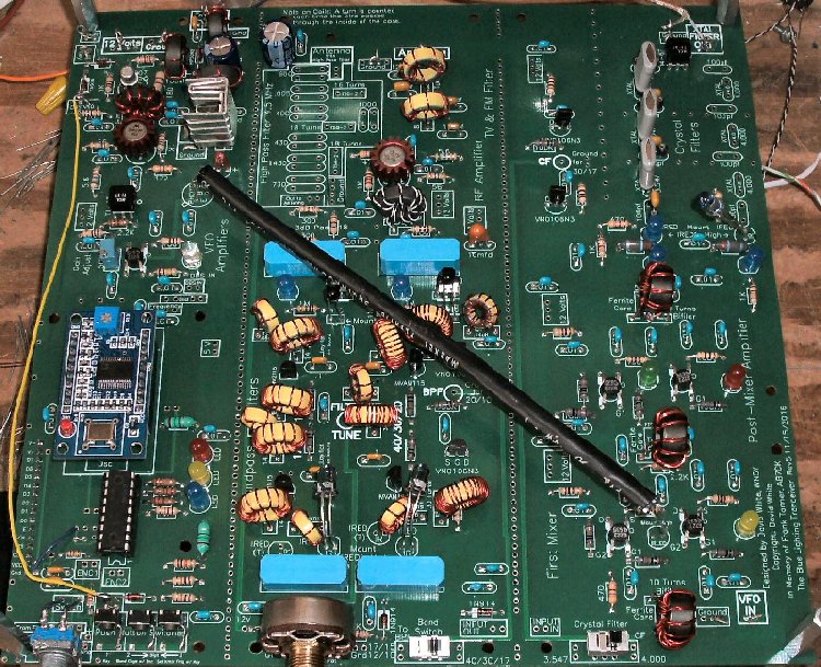
The yellow jumper between the DDS VFO and the T/R switch is the Key line for the T/R switch and the DDS VFO switch for the Receiver/Transmitter frequencies. A key/keyer is attached to a box labeled KEY a little ways behind the rear connection. Notice the black tube to carry IR light from the First Mixer to the First VFO Amplifier used as an AGC for the VFO amplifiers. Two jumpers are not shown in this image. They are both mounted below the board. 1. The coax jumper between the VFO OUT at the top of Section 1 (VFO) that goes to VFO IN at the Mixer is run underneath the board to keep it out of the way of the IR paths in the Bandpass Filters. 2. The jumper from the center of the Bandpass Filters is run underneath the board so it is easy to connect to the Bandpass pot soldering lugs, which are underneath the board. |
Send E-Mail || Amateur Radio Receivers || Blue Lightning Transceiver
