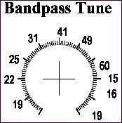
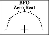
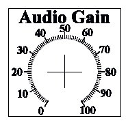
DDS VFO || Bandpass Filter Tune Potentiometer || BFO Adjustments || Labels ||Audio Control
SWL/PIC EL DDS VFO InstructionsPushbutton OperationStarting at the rotary encoder, the switches are labeled 1, 2, and 3. Operation when ListeningWhen the receiver is first turned on, 41 Meters will be the displayed band. After the first turn on, the last band/frequency will be saved and loaded on start up. To change bands, hold down Button 2 (middle button) and turn the encoder (within one second) to the band you want. You will be at the start of the band - XX.000 The default digit will be the .01 digit, and tuning will be fairly slow through the band. If you want to scan the band quickly to find signals, push button 3 (right hand button) and it will move to the .1 digit for quick tuning through the band. When you find a signal you wish to tune in, push button 2 (middle button) to move the cursor to the .01 digit and you can tune in the signal precisely. Whenever either Digit button (PB2 or PB3) is held down, it will start to scroll through the digits in the direction is in intented to go. By using this feature, you can go to the digit you want with the knob switch without having to use one of the buttons. PB1CALIBRATE MODE is entered if PB1 is pressed during power-on. See Calibrate Mode below for instructions for calibrating. Otherwise, this button is not used for the SWL receiver. PB2Cursor to RightMomentary depression moves cursor to the right one decade position. The cursor will wrap from the 1 Hz decade to the highest decade. Holding down for one second will start automatic movement of cursor to right every 1/8 second. Band ChangeDepressing PB2 and moving encoder before one second will enter band change mode. Moving the encoder will cycle through all the bands configured and releasing PB2 will select last band displayed. PB3Cursor to LeftMomentary depression moves cursor to the left one decade position. The cursor will wrap from highest decade to 1 Hz decade. Holding down for one second will start automatic movement of cursor to left every 1/8 second. Tuning Range of the DDS VFOThe bands are chosen with the DDS VFO by pushing Button 2 and turning the DDS VFO knob within one second. The DDS VFO will scroll through the bands until it reaches the one you want and and release Button 2. The bands on the DDS VFO are 60 Meters (4.750 MHz), 49 (5.900), 41 (7.100), 31 (9.400), 25 (11.600), 22 (13.500), 19 (15.100), 16 (17.480), and 15 (18.900). The next band shows 0 and is a general coverage band that has the offset programmed (plus 3.546 MHz) and can be used to go to any frequency between the limits of the Bandpass Filters, below 60 to 10 Meters. The next band is 200kHz, which does not have the offset programmed and is a signal generator that outputs the exact frequency it is showing. It is used to determine the center frequency of the crystal filters so it can be programmed into the offset frequency. This procedure is not necessary as it has already been done, but is shown here in case you change crystal filter frequencies. To use this function, tune the 200kHz band near the frequency of the Crystal Filter frequency and peak the output at the S-Meter. Use the 100 Hz or 10 Hz tuning digit to find the peak. The peak frequency is then the offset frequency put into the programming for the bands. The Band numbers showing on the display go from 1 to 11, 4.750 to 18.900 (60 to 15 Meters). Calibration ModeCALIBRATE MODE is entered if PB1 is pressed during power-on and remains pressed during calibration. The display is set to 10 MHz and remains fixed, even as adjustments are being made. If pushbutton is held pressed, then turning the shaft encoder will increase or decrease the value "osc" used to calculate the DDS control word. The basic calibrate adjustment rate is very low (on the order of a few cycles per turn of the encoder). A somewhat faster adjustment speed is available by pressing the encoder shaft or PB 3 down while turning. An external frequency counter on the DDS output is required to observe this adjustment. Alternatively, tune a receiver to the 10 MHz WWV broadcast and zero-beat the carrier. To exit calibrate mode, release the pushbutton and turn the shaft encoder one more time. The calibrated value of "osc" will then be stored in EEPROM memory. |
Send E-Mail || Amateur Radio Receivers || Back to SWL Instructions for the Blue Lightning Transceiver