
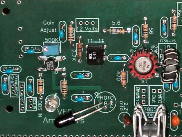
| The DDS Amplifiers to of Board 1 are shown above. The gain adjustable MOSFET amplifier is on the left and the 2N5109 amplifier on the right. The 5V regulator (tab heatsink) with capacitors for the DDS is on the bottom right. |
MOSFET AmplifierThe first amplifier is a gain controlled MOSFET with the gain control on Gate 2 of the MOSFET. The 500K trim pot sets the sensitivity of the BXP38 light receiver. When the BXP38 receives light, the resistance of the BXP38 lowers, lowering the bias voltage of Gate 2 which lowers the gain of the MOSFET amplifier. Less light on the BPX38 increases the resistance and raises the voltage on Gate 2 which raises the gain of the MOSFET. Maximum gain is at 6 volts and minimum is 0 volts. It is not linear in range, but between 4 and 6 is where most of the gain range occurs. The other side of the IR controlled MOSFET if the IR emitter at the First Mixer. The IR emission depends on the DDS drive to the mixer. High drive levels increase the IR emissions and low drive levels reduce IR emissions. As the IR increases to the BPX38, the gain of the MOSFET lowers, and as the IR decreases, the gain of the MOSFET raises. This AGC action is set by the 500K trim pot. The best level found for flat response between the 40 to 10 meter range of the receiver was 4 volts P-P at the output of the DDS amplifiers. This level is set by the 500K trim pot. |
Send E-Mail || Amateur Radio Receivers || Blue Lightning Transceiver
Last Update: 6/8/2018
Web Author: David White, WN5Y
