|
Different sizes of spacers and screws will be sent with the kit. Spacers that fit 4-40 screws will not need any modifications. Spacers that fit 6-32 screws will need the following modifications:
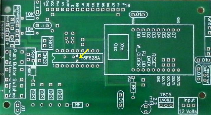
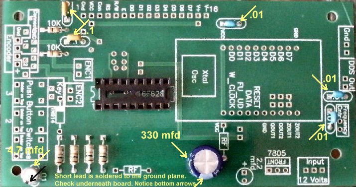
Note: If you are mounting this board on an ELR with the spacers/screws sent with the kit, drill the holes at the corners as shown below. ____1 - 9/64" Drill bit and drill Drill the four holes near each corner of the board, marked with an arrow, with the 9/64" drill bit. |
|
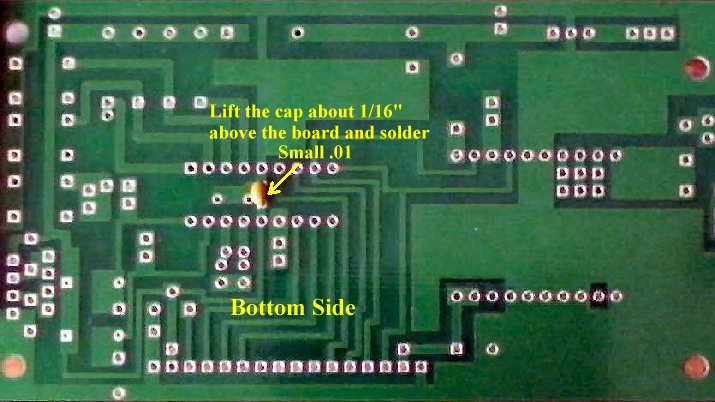
____1 - Narrow .01 capacitor, This cap has .02" pin spacing and goes in the exact middle (four pins on each side of the cap) of the PIC on the bottom side of the board to bypass the B+ to Gnd. It is placed in two holes between the two rows of pins for the PIC. Look carefully in the picture below to locate where it is placed. Lift the capacitor about 1/6" above the board and solder. Bending the leads on the opposite side of the board can hold it in place while soldering. |
|
After soldering, clip the leads as close to the board as you can. |
|
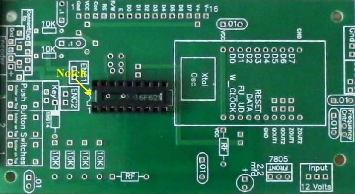
____1 - 18 pin socket for the PIC. Notice the notch on one end of the socket and match it to the notch on the footprint on the PCB. Note! Make sure the socket fits flat against the board. If not, clip the capacitor leads closer to the board. Solder two pins to the PCB (diagonal opposite to each other), while holding the socket against the top side of the PCB. Then solder the other pins. |
|
Use a magnifying glass to double check your soldering on the socket pins. 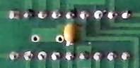 |
|
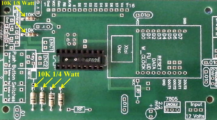
____4 - 10K resistors 1/4 Watt, Bend leads slightly away from the body of the resistor for easy insertion. |
|
____1 - 4.7 mfd Electrolytic capacitor, put in the place of the narrow .01 footprint. Short lead, negative pin, is soldered to the ground plane, see picture below. |
|
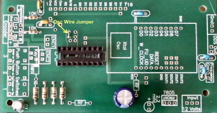
____1 - 1 inch wire jumper, a cut resistor lead will work This wire sets the Oscillator for the PIC. This oscillator type is 'Internal Oscillator and the frequency is set by a resistor from Pin 3 to ground. In this case the resistor value is zero, which sets a Frequency of 10.4MHz for the Internal Oscillator. This allows the use of either an optical (128 step) or mechanical encoder (24 step). The Configuration Word for this Oscillator is ER_OSC_NOCLKOUT. Notice the other solder points around this area, Pin 3 and Pin 4 of the PIC. This allows putting in a Crystal Osc function if desired. The internal oscillator was used because it radiated the lowest RF signal from the PIC, making it quieter to use with the receiver. |
|
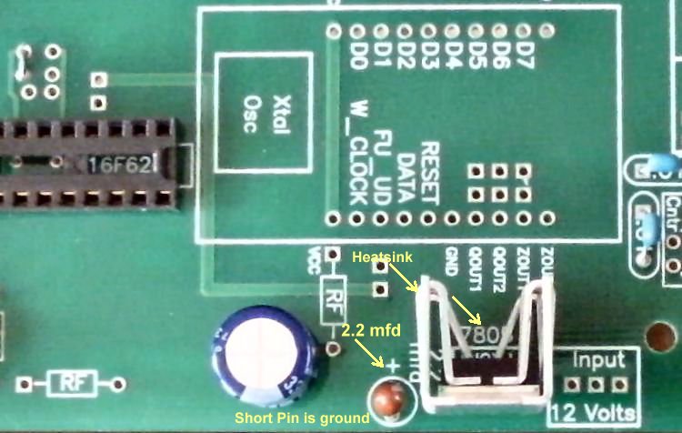
____1 - 7805 Regulator, Front of part is oriented toward center of board. |
|
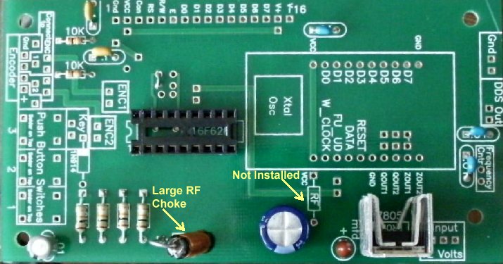
____1 - Large RF Choke, mounted vertically |
|
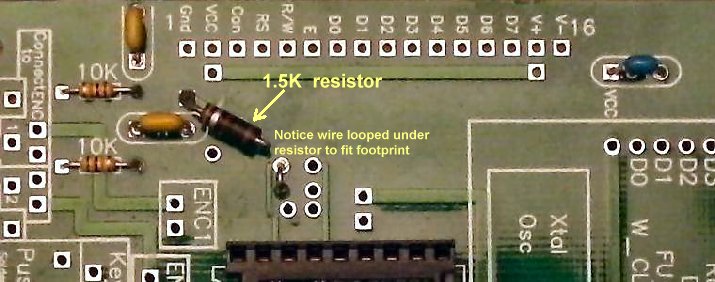
The following may have already been done. Check to make sure the trace is cut with a multimeter to see that there is no connectivity between the holes. Notice in the following picture where a trace is cut. This trace controls the brightness of the LCD. Some of the LCDs shipped with the kit are too bright and you can't see the lettering with these two holes shorted. When the bright control on the LCD is grounded it runs full brightness. It was found that a 1.5K (a 1K, 1.2K or 1.5K) resistor provides the right brightness for all the LCDs shipped with the kit so this trace needs to be cut and the resistor soldered in the holes on each end. Use a utility knife and cut through the trace at an angle and then cut again at an opposite angle or straight down to cut the trace. Check with a multimeter to make sure the trace is cut. |

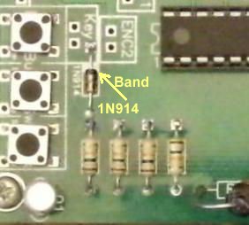
____1 - 1N914 Diode, match Black band of Diode to the white band on the footprint
 |
|
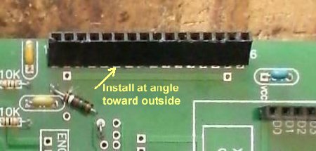
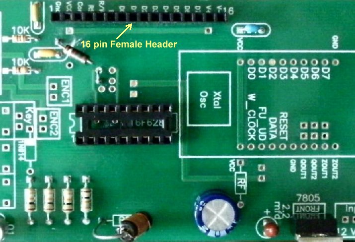
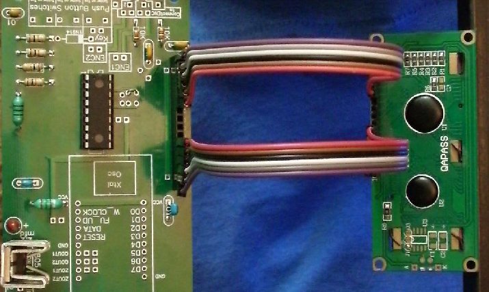
Check with a magnifying glass to make sure all solder joints are good. There are several ways to connect the display to the board. This one uses a 16 pin female header on the PCB. Two 6 pin male/male cables are soldered to the display. The other end of the double male cables are plugged into this female header. The outer 6 pins on both sides of the 16 pins are used. Two 6 pin Male/Male cables are supplied with the kit are about 9" long. Colored wires help to connect the cables correctly (Pin 1 and Pin 16) at both ends. |
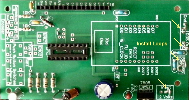
| ____3 - Loops, 1 1/4" inch bare wire bent into a loop. See Construction - Making Loops |
|
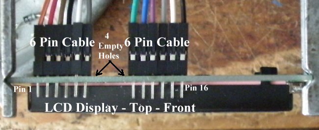
____1 - LCD Display, 16 by 2, blue background with white letters. ____2 - 6 pin male cablesNOTE: Pin numbers - 1 and 16 - are clearly marked on the back of the display. Solder or connect the two 6 Pin cables to the display on each end of the 16 Pin footprint. Make sure there are no crossed wires! They should all be in a row. If you find a crossed wire after soldering, since they are individual connectors, you can remove the ones crossed easily and correct the error. |
|
____1 - 16F628A PIC Chip Follow the next two steps:1. Install the 16F628 PIC. The pins may be spread out slightly. Press them together so the PIC installs into the socket easily. Note the notch on one end of the chip and match to the notch on the footprint and on the 18 pin socket. 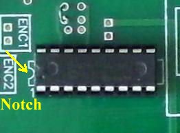 2. Hook up the display to the PCB (Pin 1 to Pin 1 and Pin 16 to Pin 16. Note the orientation of the boards. There will be four empty holes between the cables on both the DDS VFO PCB and the display. |
|
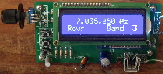
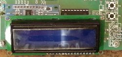
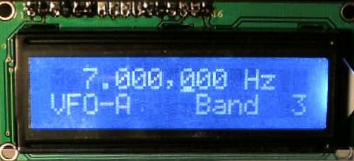
Apply 12 Volts (with clips) to the 12V connection on the right side of the 7805 regulator (opposite the tantalum cap) and Ground connection to the ground plane on an edge of the board. The Display should light up and you should see what is shown in the picture below. |
|
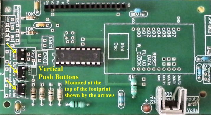
____3 - PC mount Push Button Switches. |
|
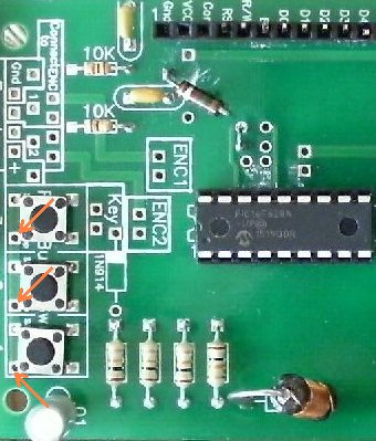
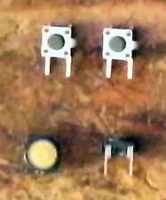
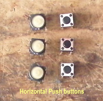
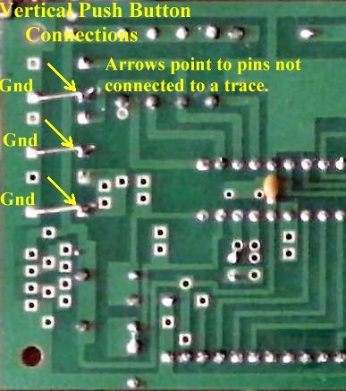
There are three kinds of Push Buttons, one vertical and two horizontal. The vertical ones have two leads (Upper left hand picture) and the horizontal have four. The horizontal ones have two leads connected to one side of the switch and two leads connected to the other side of the switch. The vertical buttons need a jumper to ground one side of the switch. The picture below shows the vertical ones, both top and bottom. The jumpers needed are shown in the following picture. Notice that the pins not connected to a trace are jumpered to ground (Holes on the left side as shown in the picture). |
|
The black horizontal ones (with large white buttons) are soldered onto the board with no modifications. They drop into the holes for the switches. The silver ones with the small buttons need one pin cut off before soldered onto the board. Notice the red arrows in the picture below and the pin that needs to be cut before mounting onto the board. They may already be cut before shipping.
Be careful pushing them into the board to get them to set flat on the board. |
|
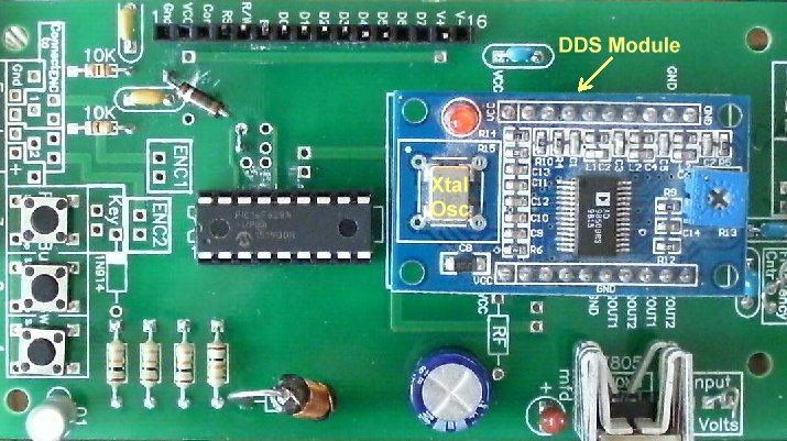
____1 -China DDS Module. Notice location of the Xtal Oscillator and match it to the footprint on the PCB. Also, the outline of DDS footprint should match placement of the module. Push the module through the holes and solder. |
Temazepam 30mg 180 pills US$ 610.00 US$ 3.39
Temazepam 30mg 30 pills US$ 160.00 US$ 5.33
Temazepam 30mg 360 pills US$ 1,040.00 US$ 2.89
Temazepam 30mg 90 pills US$ 320.00 US$ 3.56
| Königstein | Braunlage | Zerbst | Maintal |
| Clayton | Paradise | Willow Park | Temazepam Manchester |
| Philippi | Moscow | Snohomish | Temazepam Bastrop |
|
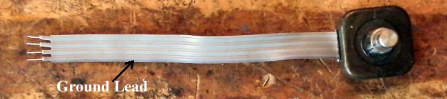
____1 - Optical encoder First, trim and tim the leads at the end of the cable as shown below about 3/16" long. Notice the black lead on one side - that is the ground. Note: Best to tin the leads before inserting into the PCB holes. The stranded leads of the Encoder are very thin and if they hit the edge of the hole, they will bend, making it difficult to insert. Trying to twist the strands together can be difficult. Right after trimming the insulation off a lead, tin immediately. |
|
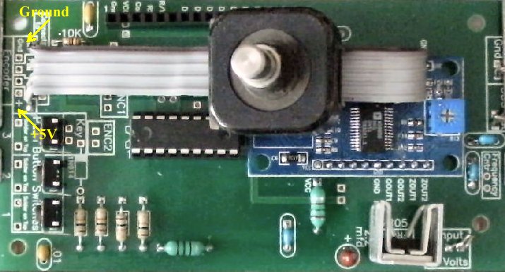
Solder the leads onto the DDS VFO board. Notice the Ground and + leads are on opposite sides of the cable. Solder them to the board as shown below. You may find that holding the encoder against the top of the board (the board being upside down) will keep the leads in the holes while soldering on the bottom side. Solder the Gnd and +, first, then the cable will be held to the board while soldering the center leads. Be careful handling the Optical Encoder leads, as they break easily with too much movement. |
|
____1 - Mechanical Encoder It is easier to use a mechanical encoder if you are going to use it on top of ELR Board 1 above the VFO. The pins for connecting the mechanical encoder with a center pin ground are not correct on the board. The left pin of the encoder is straightened out and the ground (center pin) is inserted in the Ground plated through hole as shown below. 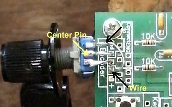 Clean the green solder mask from underside the board where the tabs on each side of the mechanical encoder touch the bottom of the PCB. The tabs will be soldered here to provide stability for the encoder. 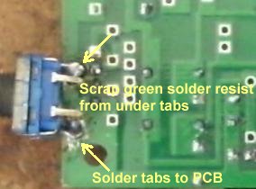 ____Solder the center pin (Ground) and right hand pin (to the hole in the box labeled number 1) of the encoder to the board while holding the tabs against the underside of the PCB. 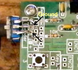 ____Solder the tabs |