|
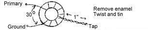
C1 and L1 compose a trap which is used to prevent 10MHz WWV from getting into the IF filter. The trap should be replaced with a wire when using crystal filters other than 10MHz. If you want to hear WWV, just place a jumper between the "ANT" and pin 3 of the T4-6T transformer on the PCB between the NE602 (U1) and the crystal filter. The input coil has two windings. The primary is wound first (Part A). Then the secondary is wound over the primary (Part B). A. Input Toroid - Primary Winding
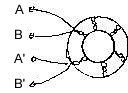
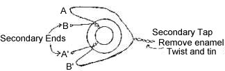
Cap Across C2 - Place across C2 on copper side of board. Install when placing the toroid on the board. Mark the primary wires with a piece of tape so they will not be confused with the secondary winding. B. Input Toroid - Secondary Winding Wind 10 bifilar turns over the primary winding - same for all the bands. 1. Take two wires, 12 inches long 2. Twist the two wires together leaving 1" leads at each end. 3. Wind twisted pair over the primary - 10 turns
4. Trim extra lead length. Scrape the enamel from the ends (about one inch) with fine sandpaper, knife or razor blade.
5. Connect A to B', this is your secondary tap.
|
Return to Amateur Radio Receivers ||
Beginner and Experimenter's Receiver Kit
|| Send E-Mail