|
This step gives instructions for winding the two coils for the kit, the input coil and the VFO coil.
Both coils use a T80-6 (or T68-6) toroid supplied with the kit. Wire size is not critical. Larger sizes (#22 - #24) are easier to handle. Sizes #20 to #28 will work.
The input coil has two windings. The primary is wound first (Part A). Then the secondary is wound over the primary (Part B).
The VFO coil has one winding with a tap. Instructions are in Part C.
A. Input Toroid - Primary Winding
| Band |
Cap Across C2 |
Turns |
Tap From Ground |
Wire Length |
| 80 |
300 pf |
40 |
4 |
40" |
| 40 |
none |
40 |
4 |
40" |
| 30 |
none |
30 |
4 |
32" |
| 20 |
none |
20 |
4 |
22" |
| 17 |
40 pf |
12 |
3 |
14" |
| 15 |
none |
12 |
3 |
14" |
| 12 |
none |
10 |
2 |
12" |
| 10 |
none |
10 |
2 |
12" |
Cap Across C2: 80 and 17 Meters only - Place across C2 on copper side (back side) of board. Solder to the solder points of C2. Install when placing the toroid on the board.
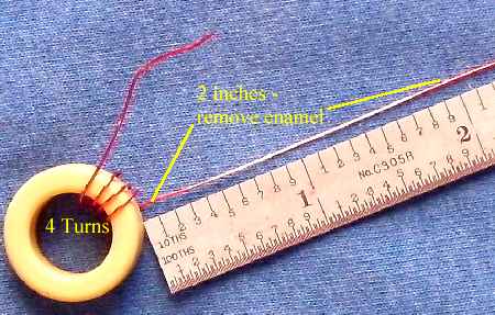
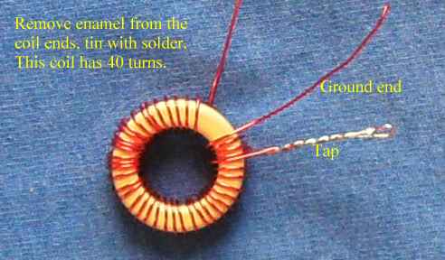
Wind the first four turns on the core. Stretch out 2 inches of the wire. Scrape off 2" of the enamel to make the tap. Fold over the 2" length to make a one inch tap.
Remember to count the turns that go through the center of the core for the actual count of the turns.
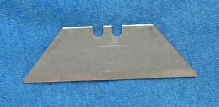
It is best to scrape the enamel off with a utility knife blade while rotating the wire. Use just enough pressure to remove the enamel. Too much pressure will niche the wire and possibly cut the wire.
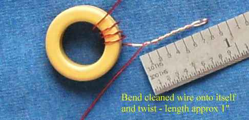
Bend the cleaned wire onto itself and twist together. The tap should be about 1" long - not critical.
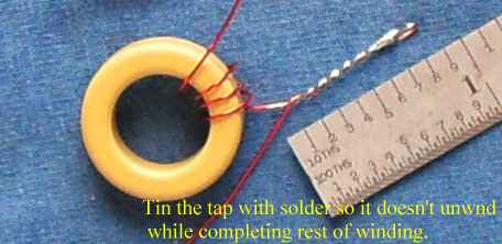
Tin the tap with solder to hold it in place. Also makes it a lot easier to solder into the PCB hole. Cutting the tip off the tap may be necessary so it can slip into the PCB hole.
Clean the enamel off the two wire ends of the coil. Tin the ends so soldering them to the PCB holes will be easy. Length of the ends can be cut to about 1". The ends of the coil can be spread apart to about a 30 degree angle. This is not critical at all. The picture above shows a gap the is much less the 30 degrees, probably 15 degrees.
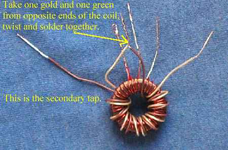
B. Input Toroid - Secondary Winding
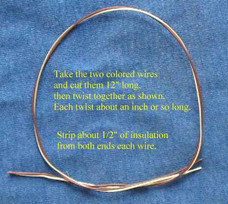
There a two colored insulated wires in the kit: one gold and one green or blue. Cut a length 12" long from each color. Twist them together as shown above. Twisting them closer together at the ends to keep them together may be necessary, especially when winding them on the core.
Strip 1/2" of insulation of all the ends. The insulation is molded onto the wire pretty tight. A wire stripper can be used but hold the wires tightly. Using a utility knife blade and stripping the insulation lengthwise may be necessary.
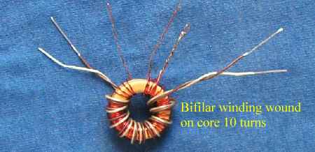
Wind ten turns of the bifilar wire on the coil. Start with about an inch of wire length through the center of the toroid as shown above.
Remember to count the turns that go through the center of the core for the actual count of the turns.
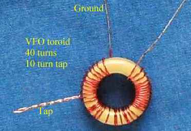
C. Wind VFO Toroid - Wound same as Primary Coil pictures above but uses a different number of windings.
Tap for 40 Turns, 10 Turns
Tap for 20 Turns, 5 Turns
The tap is counted from the ground end. Find the toroid information in the first chart, value for C35 in the second chart.
Toroid Turns
| Band |
Crystal |
VFO Freq |
Toroid |
Wire |
Align with |
| Mtrs (MHz) |
MHz |
MHz |
Turns |
Length |
Tuning Cap |
| 80 (3.5) |
10 |
6.5 |
20 |
21" |
Open |
| 40 (7.0) |
10 |
3 |
40 |
40" |
Open |
| 30 (10.15) |
4 |
6.15 |
20 |
21" |
Closed |
| 20 (14.0) |
10 |
4 |
40 |
40" |
Closed |
| 17 (18.06) |
10 |
8.06 |
20 |
21" |
Closed |
| 15 (21.0) |
16 |
5 |
40 |
40" |
Closed |
| 12 (24.89) |
16 |
8.89 |
20 |
21" |
Closed |
| 10 (28.0) |
20 |
8 |
20 |
21" |
Closed |
When winding coils with 40 turns, make a tap 10 turns from the ground end of the coil. When winding coils with 20 turns, make a tap 5 turns from the ground end of the coil. See pictures for the Primary Input coil for winding a tapped winding. A secondary winding is not used for the VFO coil.
Please note that the turns for the coil before the tap will be different than shown in the pictures. Instead of 4 turns, it will be either 10 (40 turn coil) or 5 (20 turn coil).
C35
| Band |
C35 |
C32 Range |
C32 Set |
Tuning Cap |
Range* |
| Mtrs (MHz) |
Cap |
MHz |
MHz |
Wide (kHz) |
Var Cap |
| 80 (3.5) |
220 pf |
6.1-6.9 |
6.5 |
500 |
50 |
| 40 (7.0) |
300 pf |
2.9-3.2 |
3 |
175 |
20 |
| 40 (7.0) |
330 pf |
2.8-3.1 |
3 |
175 |
20 |
| 30 (10.15) |
220 pf |
6.1-6.9 |
6.15 |
500 |
30 |
| 20 (14.0) |
120 pf |
3.5-4.2 |
4 |
576 |
15 |
| 17 (18.06) |
100 pf |
7.6-9.4 |
8.06 |
1290 |
100 |
| 15 (21.0) |
100 pf |
4.3-5.2 |
5 |
|
135 |
| 15 (21.0) |
47 pf |
4.2-5.4 |
5 |
918 |
|
| 12 (24.89) |
100 pf |
7.6-9.9 |
8.89 |
|
200 |
| 12 (24.89) |
47 pf |
7.7-9.7 |
8.89 |
1808 |
|
| 10 (28.0) |
100 pf |
7.6-9.4 |
8 |
1290 |
100 |
|