VFO Modifications || Crystal Filter Modifications
Crystal Oscillator/Amplifier/Mixer Modifications || AM Detector/Audio AGC Amplifier


|
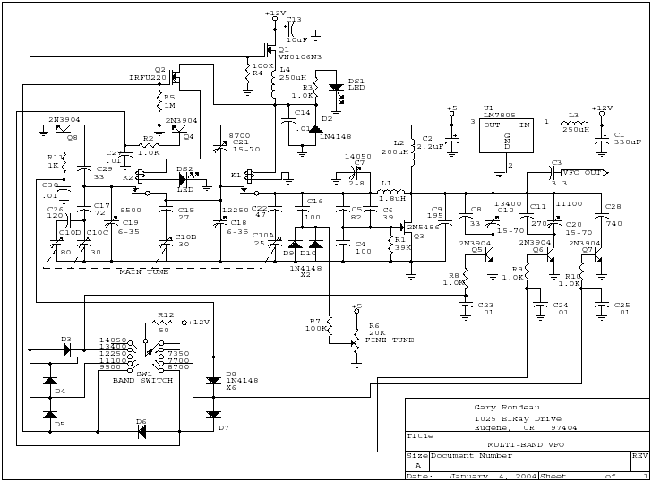
Gary modified the VFO to cover 8 bands using the existing VFO. He added 2N2904s to switch in more capacitance at both relays to reach the additonal bands. Addtional trimmers were added and four sections of the tuning capacitor were used. Switching is done by a rotary switch with 1N4148 diodes to make sure the right VFO frequency was activated. |

|
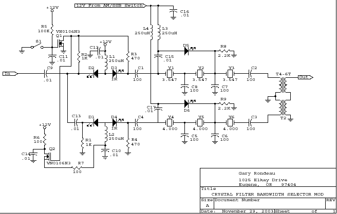
A very simple way of switching crystal filter bandwidth. When the AM/SSB switch is on only one crystal is used in the crystal filter widening the bandwidth for AM reception. This circuit could be used in a combination CW/SSB ham band and AM SWL receiver. In Gary's receiver the modification allows receiving both SSB and AM signals in the SWL bands. |

|
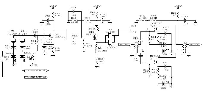
The crystal amplifier is modified and the transformer is removed. Provides more drive to the mixer and increases the gain of the mixer. Worthwhile addition to any of the Electroluminescent receivers. Notice he also includes the one crystal filters between the amplifier and the mixer. Holes are provided in Board 2 for this filter. It very effectively removes the second harmonics of the crystal oscillator and provides a very low phase noise signal for the mixer. |

|
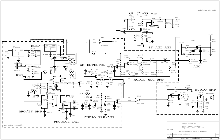
Downloading the .pdf file will be necessary to easily read the schematic. The following is a copy of the email Gary sent me with the schematic. He does an excellent job of explaining the circuit. "I came up with an audio derived AGC signal that I applied to your AGC transitor and used your timing cap for the decay. I found that I needed a fair amount of audio gain to drive the AGC so two transitors were required. "I also found that it works best with no filtering after the diode -- essentially setting the gain by the peaks detected. It was important to add a second RF filter on the input, and I biased the the frequency responce of the AGC amp toward higher audio frequencies to keep it responsive to static. "When I switch to AM mode, I power the AM detector and the Audio AGC amp and cutoff bias to the IF AGC AMP. In SSB mode, the AM detector/audio AGC amp is without power and the IF AGC Amp is provided with bias. "The output of both AGC amplifiers connect to the base of your AGC transistor through 1K resistors. The unused amplifier does not seem to bother the operation of the other one. I have an AGC level pot on the front panel fro the audio AGC. "I'll have to use it for a while to see where it works best.I initially built the AGC circuit on a bread board, but have since used the Dremel and drill technique to add the circuit to some of the available ground plane in the AGC section of the circuit board. "Using the audio-derived AGC makes SWL listening quite a bit more pleasant. You can now tune to the middle of the band and get the best signal. Fading is not as noticable. "Now with the stabilizer working better, you can tune a station, leave the room for an hour and come back and it is still perfectly in tune and sounds good!" Gary fine tuned the circuit for even better performance. The following email explains the problems and parts that were added as shown in the schematic above. "Naturally, the first AGC circuit I sent you wasn't quite right. When I put the scope on things, I discoverd lots of 455kHz in the AGC amp. "I added an RF choke and changed the detector capacitor to get rid of it. Then the AGC gain was all off so had to change all of the emitter decoupling caps to get more gain. "Then with plenty of gain, the circuit wasn't stable any more so had to add a little feedback stabilization cap... "Once it was working again, I found that to keep strong AGC action from popping too much, I had to couple to your AGC transistor with 47K (could even be larger perhaps) so the drive is not so high that it discharges the 10uF cap too fast. "Works pretty well now." |
Send E-Mail || Amateur Radio Receivers|| Electroluminescent Receiver || Details of Duncan's SWL Receiver
