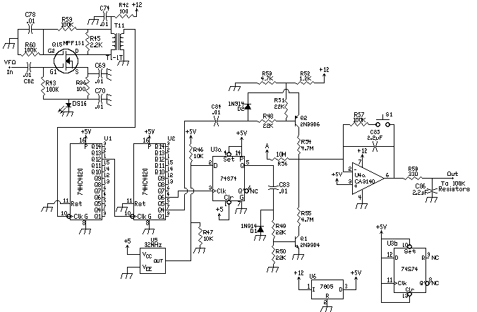


|
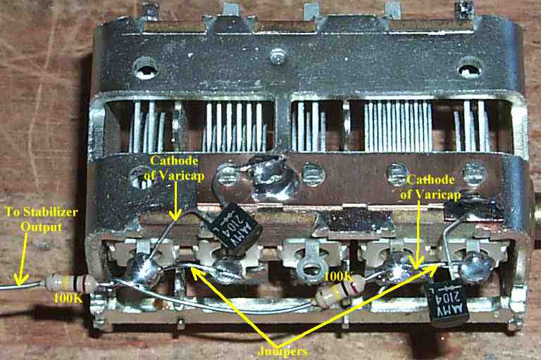
I recommend putting the two resistors in parallel instead of in series as the picture shows above. Even though they are in series above, it still works. In this technique MV2104 varicaps are mounted on the main tuning capacitor. The MV2104's have worked very well. Two varicaps and two 100k resistors are mounted on the main tuning capacitor. The mounting is done on the tab side with round holes. The 100K resistors are connected to the cathodes of the varicaps and tied together on the other end to connect to the frequency stabilizer output. Note in the picture above that the cathode of the varicaps is attached to the stator of the capacitor. The two end sections of the main tuning cap are tied together for more capacitance. A jumper wire is used to tie the sections together. They are only tied together on this side. The connections to the stator on the other side of the capacitor are used to connect to the VFO. The output of the stabilizer (labeled relay on the stabilizer board) is connected to the two 100K resistors. |


|
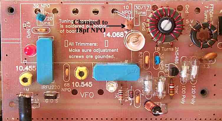
On the Ham Band version of the receiver, the 10pf NPO coupling capacitor, located next to the ceramic trim capacitor marked 14.068, needs to be replaced with an 18pf NPO capacitor as shown in the image above. This helps the stabilizer lock at all settings of the main tuning capacitor. The bandspread of the 14 MHz VFO will be a little under 300 kHz. The range of the 10 MHz VFOs will be around 250 kHz. If the receiver is being built for reception of the 40 and 20 Meter SSB bands, see SSB Modifications, "40 and 20 Meter SSB Setup" for information on using the Frequency Stabilizer. The SWL version works fine with the stabilizer and easily reaches all the required frequencies. |

Send E-Mail || Amateur Radio Receivers || Electroluminescent Receiver || Frequency Stabilizer Construction
