
| One of the best RF amplifiers ever published was Wes Hayward's post mixer amplifier in the Progressive Communications Receiver. It quickly became known as a great high level RF amplifier. With a standing current of 50ma, it takes a very strong signal to upset this amplifier. Check out page 15.24, figure 15.33 of the 2000 ARRL Handbook for Radio Amateurs for more information. |
|
This receiver is designed to work in the worst conditions that many hams have to tolerate: living in a condo or townhouse with antenna restrictions. A Hamstick antenna mounted just inside a bedroom window (in a townhouse) was used to test the sensitivity of the receiver. A 16-18dB RF amplifier was used to provide the necessary sensitivity to work with a hamstick in a townhouse/condo. When this receiver is used with better antennas, the front end gain needs to be "tuned" for the antenna system used. The RF amplifier needs to be bypassed in really good antenna systems, and maybe used only on the 17 meter band. Instructions for bypassing the RF amplifier are near the bottom of this page. In between the Hamstick and dream antenna farm, the RF amplifier is left in and a 50 ohm pad is adjusted for the right amount of gain. The right amount of gain is a compromise between sensitivity and dynamic range. When using a Hamstick, signal levels are so low that going all the way for sensitivity gives a very good performing setup. Low Noise AntennasAn excellent article that shows the effectiveness of using Hamsticks in a dipole configuration is "Receiving Antennas", by Robert L. Nelson, K6ZGQ, Ham Radio, May 1970, pp 56-63 (Subtitled: "A discussion of special purpose antennas for receiving - including some novel ideas for improved performance on the lower bands"). Low noise receiving antennas, combined with a high level RF amplifier gives the ideal receiving setup. Mr. Nelson states, from the article above (page 62), "I have obtained good results with both a helical dipole and an untuned five-foot-long dipole with a capacitive hat when worked through an antenna coupler. However, the helical arrangement is somewhat better." Again, on the helical dipole (page 62), "This antenna, if mounted horizontally, will be horizontally polarized, electrical-field sensitive and balanced with respect to ground, and will discriminate rather well against local noise." Even though this receiver has plenty of gain to work with small antennas, they must be tuned and matched to the 50 ohm input of the receiver. An antenna tuner must be used with random wires for best results. A Hamstick used at its design frequency gives the best reception. However, a 17 meter Hamstick gives even reception throughout all the bands of this receiver. My ground lead was a #12 wire to the pipes in the bathroom. A counterpoise wire run along the baseboard of a room will also work as a ground. Other Hamsticks give different results. A 30 meter Hamstick will work on 17 meters, but on none of the others. A 20 meter Hamstick will work ok on 40 meters, but hardly at all on 30. A 40 meter Hamstick will not work very well on 20 meters, etc. For general listening, use a 17 meter hamstick. In many mobile installations, several Hamsticks are mounted on a common mount. A multiple Hamstick installation would work well with the receiver. Adjusting GainTo gage proper gain at the RF stage, listen to the signal in the speaker and check for 455 kHz IF strip noise. This receiver was designed so IF noise is masked by the signal levels entering the IF strip. If you do not get a definite rise in background noise when tuning a band with the bandpass filter pot, more amplification is needed. If the band noise blows you off the table, add more loss in the 50 ohm pad. A 3dB pad is installed at the output of the RF amplifier. Higher loss pads may be used. Tests on loss/gain through the front end and bandpass filters indicate the receiver has the same gain with or without the 3 dB pad. The reason surmised is that the gain is improved by better matching with the 3dB pad versus a little mismatch that loses some signal strength without the pad. The 3dB pad is recommended in every situation. Real differences begin with a 6db pad. The 50 ohm pad used in the receiver is a Pi-Network Resistive Attenuator. The following are some values that would be useful in this receiver. Reference for this information came from the 2000 ARRL Handbook, page 30.24. Only the most recent editions of the Handbook carry this information. 
|
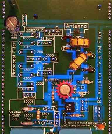
 This is the circuit used in the receiver.
This kit substitutes the 2N3019 for the 2N5109. The 2N3019 does not have the 500MHz bandwidth like the recommended transistor (ft is 100MHz), but tests with an SA and 200MHz scope have shown that it works OK. The 2N5109's are available from many suppliers in the ham market and may be ordered and put into the circuit. Tests have shown little difference between a 2N5109, 2N3019, 2N2219A, or a 2N918 with this receiver. The 2N918 does exhibit 2dB less gain than the others, but works just as well. Instructions for Bypassing the RF Amplifier One lead on three parts are unsoldered and disconnected from the bottom copper trace. First, the 100 ohm resistor at the 12 volt input. This disconnects power to the RF amplifier. Two .01 capacitors are unsoldered, one at the input of the amplifier between the input filter and amplifier. The second one is at the output of the 50 ohm dB pad. See image above, arrows point the the lead of the part to be unsoldered. A wire is run between the disconnected lead of the input capacitor and the extra hole next to the disconected capacitor at the 50 ohm 3dB pad. MOSFET Amplifier as a Front End AmplifierThe regular MOSFET amplifier was my first choice as RF amplifier for the kit. The MOSFET was used in all the early prototypes of the receiver. However, after testing with some Hamsticks for performance evaluation, I would get out of my chair, walk across the room four steps with rubber soles, and right before touching the antenna, a 1/2" static discharge would hit the hamstick. Every time I did that, the MOSFET would blow in the RF amplifier. Some efforts were made to help the situation, but nothing worked. So the MOSFET amplifier was taken out of the receiver. The transistor front end amplifier has never blown from a carpet induced static discharge. But remember, no device is immune to lightning strikes! I also found that the gain of the MOSFET amplifier decreased above 14 MHz and would be unity at 18MHz. This was using the 1:4 T4-6T transformers. In all fairness, the transformer in the RF MOSFET amplifier from the Progressive Communications Receiver was a 20:1, but even when that was tried, it helped some, but did not cure the loss of gain over 14MHz. This is not consistent with Wes Hayward's tests of his RF amplifier, but I did not investigate why mine lost all gain over 14MHz. After working with both RF amplifiers, I no longer use the MOSFET in the front end of my receivers. The Norton loss-less amplifiers, the one above, and the simple FETs are more reliable. ReferencesThe 2N5109 amplifier can be simulated using the Serenade SV program. Information on using the program and simulating the amplifier can be found at "Simulating Circuits and Systems with Serenade SV", by David Newkirk, W9VES, January 2001, QST, Page 37. The file for the amplifier is SerSV0101.ZIP at http://www.arrl.org/files/qst-binaries/ Go down to 2001 and it is at the bottom of the page. The Ansoft Serenade SV program can be downloaded at Linear RF- and Microwave-Circuit Simulation using Ansoft Designer SV Common Base Transformer Feedback Norton Amplifiers, formerly, Ultralinear 2N5109 And 2N3053 Amplifiers, Dallas Lankford, 8 VI 94, rev. 16 VI 94. An article on common base transformer feedback (CBTF) amplifiers, and also known as common base noiseless feedback (CBNF) amplifiers. If properly designed and used, offer MW DXers (and SW DXers, though their needs are not as extreme as MW DXers) amplifiers with extremely low levels of 2nd and 3rd order intermodulation distortion (IMD2 and IMD3), which, in turn, offer much higher levels of strong signal handling performance than have been available previously. Excellent article! Fixed Attenuator Calculator Online: |
Board 1 || VFO || TV & FM, BC Filters || RF Amplifier || Bandpass Filters || First Mixer & Amplifier || Crystal Filter
Send E-Mail || Amateur Radio Receivers || Electroluminescent Receiver
