
|
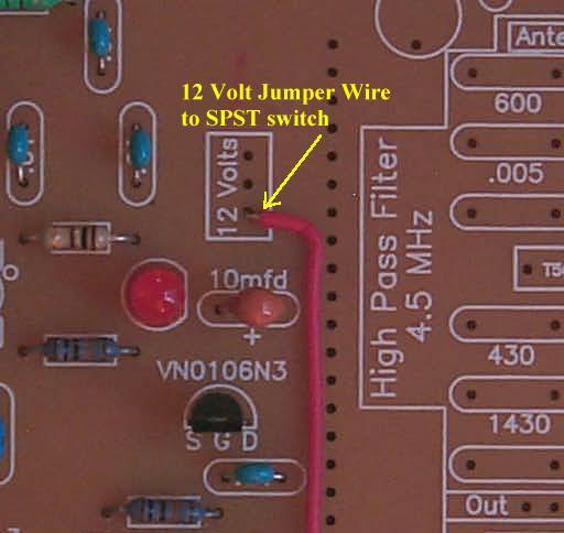
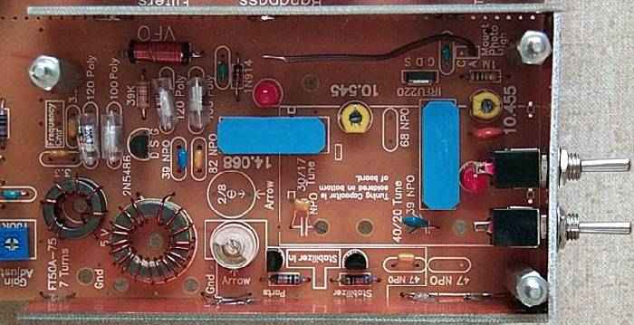
A wire is soldered to the 12 Volt box located near the top of the board to the right of the second VFO amplifier. |
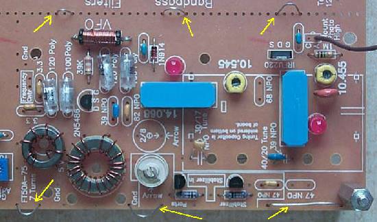
| Loops of wire (yellows arrows point to the loops) are installed around the VFO and soldered to the ground plane underneath the board. These loops are to hold the shields in place for mounting the switches. |
|
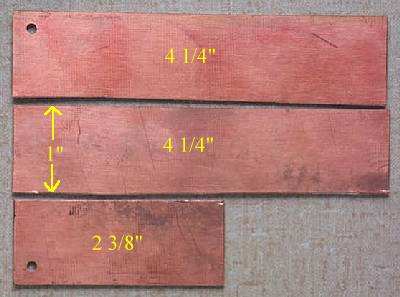
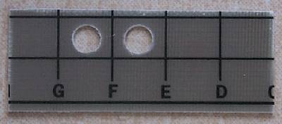
Three pieces of shield are cut. One for the front and two for the sides. Dimensions are shown in the picture. |
|
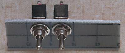
A 1/8" drill bit should be used first to make a pilot hole, then drill with a 1/4" drill bit. Be careful marking and placing the holes for the switches: do not get in the way of the mounting spacers and the adjustment for the yellow trim pot. |
|
The sides are soldered to the loops on the PCB with the spacers installed at the corner. Do not forget to install the spacers before installing the PCB boards! Also shown is the placement of the right side switch. Be sure you do not place the switch where it will cover up the adjustment for the yellow trimmer. There are no loops to hold the front piece in place, it is soldered to the two side pieces at the inside corners and provides good support. The corner spacers are taken out when the those PCB pieces are soldered together. Then make sure the spacers will still fit. |
|
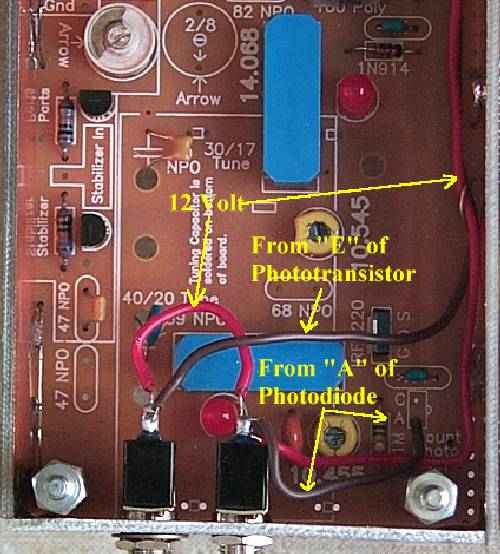
Picture shows the wiring of the switches. ____Connect the 12 Volt wire to center terminal on one of the switches.____Connect a jumper from the 12 Volt wire on one switch to the center terminal of the other switch. ____Connect the wire coming from the BPX-38 footprint ("E" terminal) to the right (looking from the front) switch terminal of one of the switches. ____Connect the wire coming from the Photodiode footprint ("A" terminal) to the right switch terminal of the other switch. |
|
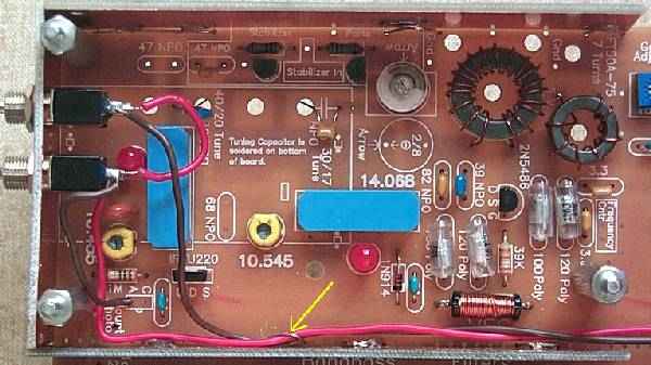
Note the arrow showing the 12 volt wire and the wire from the phototransistor footprint with a piece of wire holding them down. Movement of the wires can cause the VFO frequency to shift. Another tie point is used just past the shield. |
Send E-Mail || Amateur Radio Receivers || Electroluminescent Receiver || Construction of the Kit || Back to SWL Instructions