
|
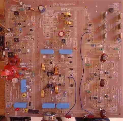
Two jumpers are not shown in this image. They are both mounted below the board. The coax jumper between the VFO OUT at the top of Section 1 (VFO) that goes to VFO IN at the Mixer is run underneath the board to keep it out of the way of the IR paths in the Bandpass Filters. The jumper from the center of the Bandpass Filters is run underneath the board so it is easy to connect to the Bandpass pot soldering lugs, which are underneath the board. |
Send E-Mail || Amateur Radio Receivers || Electroluminescent Receiver