
|
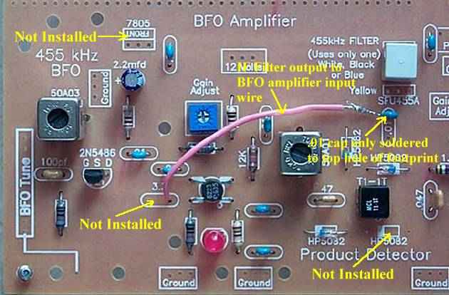
The BFO is disabled for AM SWL reception. The parts for the BFO are installed in case the BFO is desired later. The 12 Volts to the BFO is removed by not installing the 7805 regulator in the upper left of the picture. The 3.3pf coupling capacitor between the BFO and BFO amplifier is not installed. The BFO amplifier is used as an additional IF amplifier to give enough drive for the AM detector to work. A wire is run from the output of the 455kHz filter to the input of the BFO amplifier at the right hole of the 3.3pf footprint. The .01 capacitor at the output of the 455kHz filter is only installed at the top hole of the capacitor footprint and the other lead is soldered to the wire going to the BFO amplifier. At the lower right of the picture, the HP5082 diode is not installed. Removing the diode unbalances the product detector and turns it into an AM detector. |
|
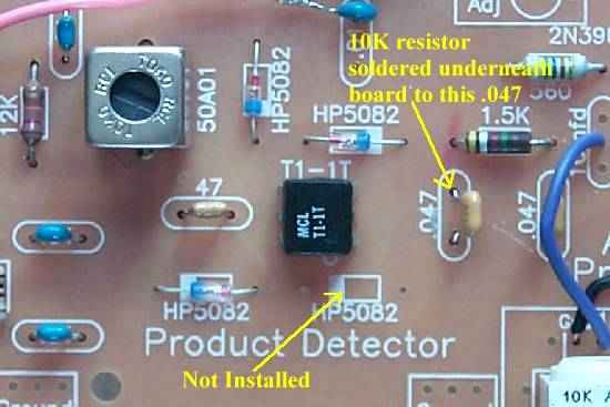
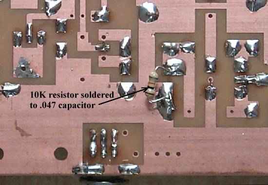
Two modifications are done to change the Product Detector to an AM Detector. First, the HP5082 diode is not installed in the lower right hand corner of the picture. Second, a 10K resistor is soldered across the first .047 capacitor at the output of the detector. The .047 mono capacitor can be easily damage by heat, so solder the resistor underneath the board. See picture below: |
Send E-Mail || Amateur Radio Receivers || Electroluminescent Receiver