
|
The description that follows is a result of my building some clear plastic cases for the Electroluminescent Receiver Kit. I have found the most important aspect of building a case is accurate cuts and holes. Before starting any cutting or drilling, practice with some scrap pieces so you don't loose any valuable good pieces of plastic or trim. The first decision that must be made is how you want to mount the main tuning capacitor. For best stability it is soldered on the bottom of Board 1, which is the best place for excellent stability of the VFO. It can be left off the board and mounted to the front of the case, but then a long connecting wire has to be run from the capacitor to Board 1, which causes some vibration problems. In all my builds, I have chosen to solder the main tuning cap to Board 1. The original mounting place puts the shaft too far back to put a large knob on the shaft after the front plastic piece is installed. So I moved the capacitor to the right and forward so that I would have plenty of shaft to mount the tuning knob. With the main tuning cap at the front of Board 1, both Board 1 and Board 2 are mounted against the front plastic piece of the case (front panel). The advantages of this mounting is that the board mounted controls can stay on the board. Accurate cuts on the front panel have to be made, but there has been enough slack so that minor errors can be made without problems. Flush mounting also provides extra stability for the boards and the front panel. The description of building this plastic case will start with the alternate mounting of the main tuning cap on Board 1, cutting the bottom wooden piece, cutting the plastic, some ideas for the back panel, then how to make the front panel cuts and logos. There are some tricks to drilling plastic and those will be explained in making the front panel. |
|
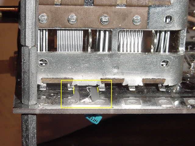
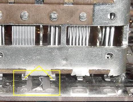
The main tuning cap has to be moved further from the edge of the board to clear the mounting spacers, and forward near the front edge. Luckily, there is enough free ground plane to move the cap easily. Make sure when soldering the first case tab that the capacitor is straight. Moving the cap after all four case tabs have been soldered can be a pain. The best way to move the cap is to use a solder sucker. Remove all solder off the tabs and then go to each tab, apply heat, then lift it slightly off the board. Repeat with each tab. Then take off all the solder on the board where the tabs touch so the cap can be accurately resoldered. Bend up the Stator Tabs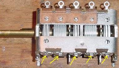 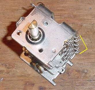 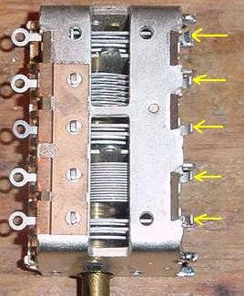 The pictures above show how the tabs are bent. Using needle nose pliers, put the pliers just a little ways on the tab and bend. If these tabs are not bent, they will short against the ground plane when the cap is soldered to the ground plane. They are just a little bit longer than the case soldering tabs on the edges of the capacitor. |
|
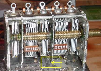
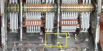
Mount the coupling capacitors that go to the VFO. The tabs are difficult to reach after the main tuning cap is soldered to the board. Notice that the caps are soldered to different tabs than when mounted in its previous position. The capacitance of the sections will be the same for either mounting position, so there is no change in the coupling capacitor values. The picture below shows the sections that are used when mounted in the original location. Note the first and last sections are used. In the new location the third and last sections are used. The first, third, and last sections are all the same value. 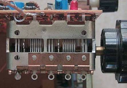 |
|
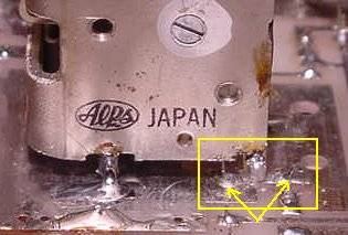
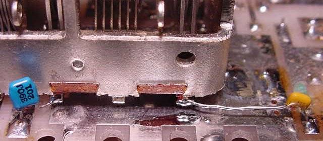
The first place to start aligning the cap is at the right rear tab. It is placed between two solder joints on the ground plane. The front case tabs are slightly back of the edge of the PCB board, then alignment is done at the right rear tab, and finally check the pictures for alignment at the side of the board and the tab on the inside of the cap. Make sure the capacitor is straight with the edge of the PCB board, check the front and side. See pictures below. |
|
Notice the tab is placed almost dead center between the two solder joints. Both solder joints are on the ground plane. Recheck the front of the cap to make sure it is straight with the front of the board. |
|
Check the outside to see if it looks like the above pictures. The inside of the two tabs in the yellow box should be aligned with the ground plane as shown in the first picture. The soldered wire on the trace in the middle will not be there. This trace is where a coupling cap will be soldered. |
|
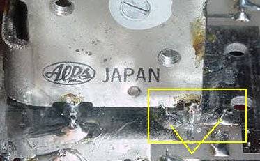
Notice the placement of the front inside tab relative to the trace. Sometimes that tab will need to be bent forward a little to make sure it doesn't touch that trace. The trace to the left of the tab must not touch the tab. Also notice that the front soldering tabs of the capacitor are not all the way flush with the front of the PCB board. The bearing housing of the rotor sticks out in front of the capacitor housing slightly and this is allowed for by backing up the capacitor slightly from the front of the PCB board. Tin the soldering tabs on the capacitor before mounting on the PCB board. Leave some extra solder on the side of the tabs so you can use it to tack the capacitor to the board before soldering all four tabs. Barely solder one tab to the board and carefully check your alignment. If OK, use plenty of solder on the tabs and ground plane to get a good solid mounting. Best way to make sure you get a good joint is to melt the solder on the tabs first, then run it onto the ground plane. If the soldering gun is placed on the ground plane and against the tab, sometimes the solder will not adhere properly to the tab because the tab will not get hot enough to accept solder. By getting the solder to adhere to the tab first, you will assure a good joint. |

|
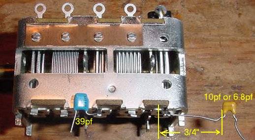
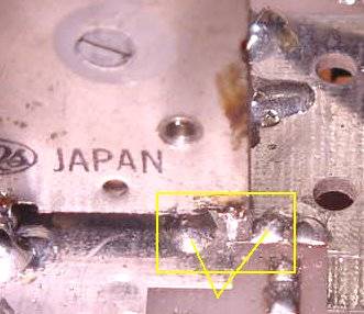
Note the traces that the coupling caps are soldered on. Be careful the wires soldered on the capacitor stator tabs do not touch the case of the main tuning cap. This is shown in the second picture. If the tabs were not bent enough, you can use a flat bladed screwdriver tip to bend them away from the PCB board, or down if the wires are touching the capacitor case. Check with a DVM to make sure if it is too difficult to see. |
Send E-Mail || Amateur Radio Receivers || Electroluminescent Receiver