
Circuit OperationThe drain of Q1 is also connected to the gate of Q2, and as long as Q1 is on, the gate voltage of Q2 is zero, which has Q2 turned off. A 1N914 is also connected to this line to prevent a gate failure from a spike when the relay switches. When the SPST switch is closed, this puts the gate of Q1 at zero volts, turning off Q1. The positive voltage through the relay and IR LED brings the gate voltage of Q2 up to 12 volts, turning on Q2. Because the impedance of the gate is so high, no current is drawn and the relay/LED cannot turn on. With Q2 turned on, 12 volts flows through the drain to the source and activates the 20/17 BPF output relay. The ground circuit of the output relay turns on two IR LEDs, which turn on the 10.455 VFO relay, and the input relay to the 20/17 BPF. Curing RF ProblemsAll the SPST switch connections have a .01 capacitor to ground. Without this capacitor, the gate lead of the VN0106N3 and the large connection pad area picks up RF from the BPF, amplifies it, and places it on the 12 Volts line. Since the 100K gate resistor does not pass RF, the gate of the MOSFET will pick up RF. This is also true at the Crystal Filters where a very similar circuit is used. If you are using long wires to a front panel switch, wire a .01 bypass capacitor to ground right at the switch to make sure all RF is bypassed. Replacing the SPST Switches with IR Switching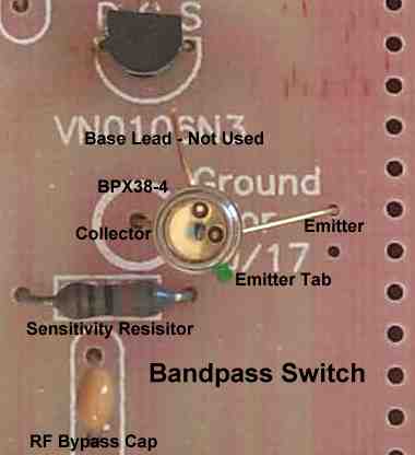 The SPST switch connection is also set up to be used for infrared communication. A phototransistor's "C" terminal is connected to the "Ground for 20/17" soldering pad, and the "E" terminal is connected to the ground terminals on the other side of the text. Since the bandpass switch connection is very close to the front of the board, there should be no problem firing it up from a front panel IRED. A phototransistor is recommended as the IR receiver to use. A photodiode, placed ccrrectly in the same holes, will have to be turned 180 degrees in order to point in the right direcion. Sensitivity is adjusted by the resistor to 12 Volts, R1 (100K) in the schematic. The resistor value is increased for greater sensitivity. The best steps to try are 470K, 1M, and 2M. You can drive the IRED on the panel with a 470 ohm resistor and be able to get it within reasonable distances with the stock 100K resistor, probably 6" to 8". At higher sensitivities, with a 470K and higher resistor, the IR path will need tubed to prevent ambient light from triggering the phototransistor. 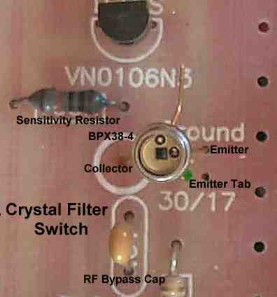 The image shows the correct installation of the phototransistor at the Crystal Filter Switch. The crystal filter switch is 6" to 7" from the front of the PCB, and may need more IR from the emitter, or an increase in the sensitivity of the IR receiver. For maximum output of the IRED (50MA), use a 270 ohm, 1 watt resistor. If the distance is going to be more than 6", best reliability will result with a 470K sensitivity resistor, and use a black tube to cover the IR path. If covering the IR path is not done, raise the output of the IRED to it's maximum with a 270 ohm resistor. Commercial Matched Pair Emitter/Receiver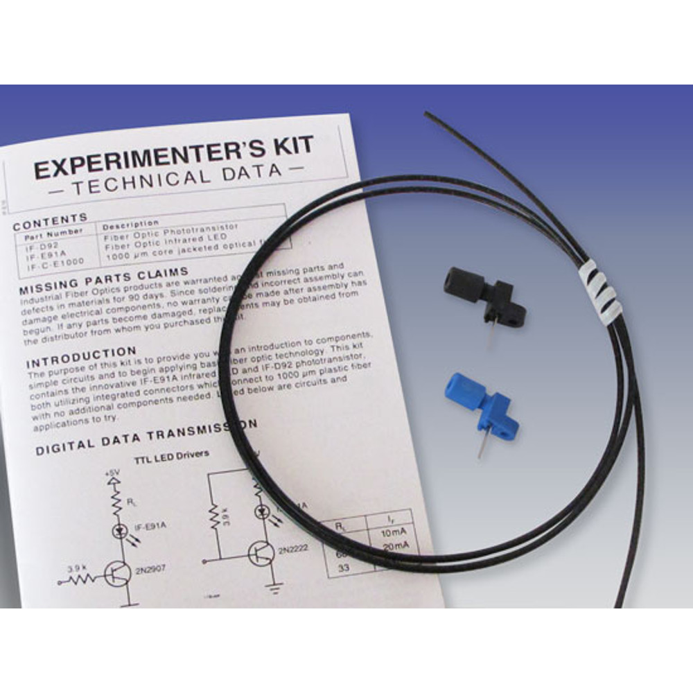 A commercial matched pair emitter/detector with 1000um optical fiber cable will also work. Drive the IRED emitters on these parts through a 1K or 470 ohm resistor. Some of these can be driven harder. Be sure to check the specs on the devices you get. Since this setup is completely shielded from ambient light, the gate resistors on the IRFU220/VN0106N3's can be replaced with 470K resistors for best performance. However, the stock values already on the board have worked fine. |
Send E-Mail || Amateur Radio Receivers || Electroluminescent Receiver || Infrared Switching Home Page
