
|
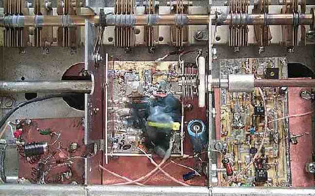
The center compartment holds the VFO. A relay is tie wrapped to the VFO toroid, which is connected to a magnetically coupled Huff & Puff Stabilizer. The relay and toroid are covered with candle wax to provide mechanical stability. The board in the right compartment are two MOSFET VFO amplifiers. The circuit boards for the VFO and MOSFET amplifiers were taken from "surface mount" prototypes made during the development of the Electroluminescent Receiver. |
|
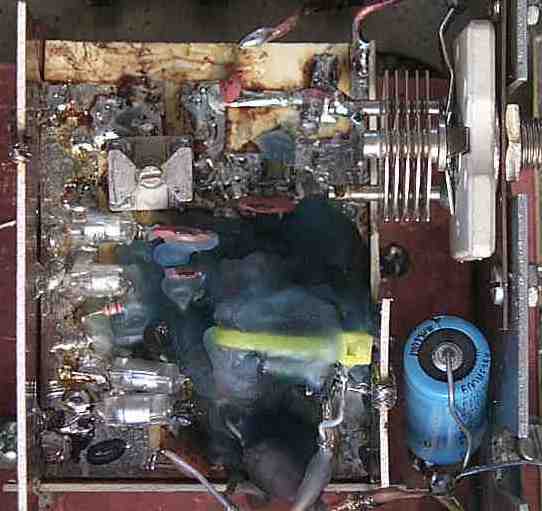
The panel mount variable capacitor at the top right is adjusted from the front panel to make adjustments to the VFO on the fly. This capacitor was used as an antenna trimmer in the stock HQ140X. The VFO only covers about 80 kHz, so this capacitor makes roaming through the band a lot easier. It was also used to set the VFO to work with the 40 meter band, when a 40 meter bandpass filter was installed in the receiver. The large electrolytic capacitor at the lower right and the smaller .01's nearby are used for power supply filtering, very important for this part of the receiver. The relay (tie wrapped to the VFO toroid) was a small square one, with all the switching parts removed. It fit perfectly on the T68-6 toroid, and is wired to the Huff & Puff stabilizer with 75 ohm miniature coax cable. The cable was also enclosed in wax to keep it from moving around and causing frequency shifts. An RF choke is directly below the cable, feeding 12 Volts to the VFO, and it was also covered with a thick coat of wax. Experiments have shown that temperature changes in the RF choke affects VFO stability. The VFO is run at 5 Volts, supplied by a regulator (7805) that is located below the large electrolytic capacitor. See image at the top of this page. |
Tramadol 50mg 60 pills US$ 160.00 US$ 2.67
Tramadol 50mg 90 pills US$ 190.00 US$ 2.11