
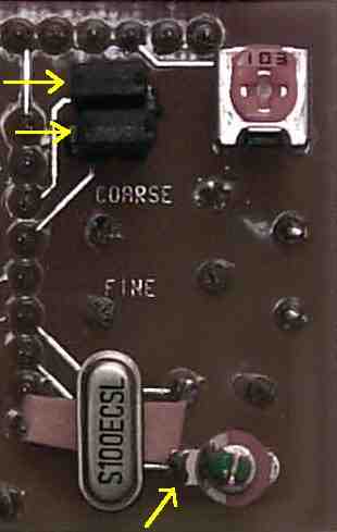
 That is a piece of paper underneath the crystal so that I wouldn't accidently pull the crystal to the PCB board and ground the trace underneath it, as noted in the instructions. Pull the paper out after you solder the crystal pins. 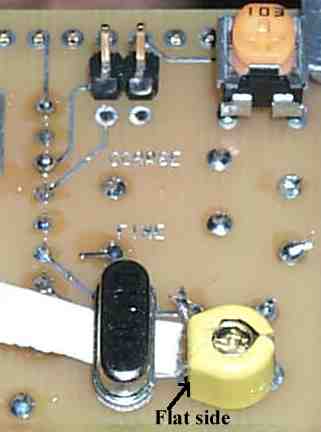 Notice the different type trimmer used on this board. Install the flat side as shown so the adjustment screw is grounded. Only one two-pin header is shown installed to show the orientation in which they are mounted - horizontally. Again, note the paper underneath the crystal to prevent pulling the crystal against the board and causing a short against the trace underneath. |
|
|
|
|
Send E-Mail || Amateur Radio Receivers || Electroluminescent Receiver || Back to DFD2 Instructions